Bal-tec™ Home Recent Developments in Ball Bar ( Dumbbell ) Technology
Recent Developments in Ball Bar ( Dumbbell ) Technology
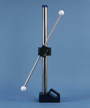
There are potentially twenty-one rigid body error sources, in a conventional Coordinate Measuring Machine. In addition, there are any number of possible elastic or bending errors, that are variations on these twenty-one errors. Eighteen of these twenty-one potential errors are geometry related, while the remaining three are associated with the measuring scales. A Ball Bar (Dumbbell) consists of two high quality balls of the same exact diameter that are securely attached to the opposite ends of a long rigid bar. This is the simplest and most accurate geometry-evaluating tool ever developed. In addition to being the most accurate evaluation device, it is by far the least expensive.
By simply measuring the uncalibrated length of a Ball Bar (Dumbbell) in a number of designated positions, throughout the machine’s measuring envelope, all of the geometry related errors will be fully evaluated. It must be understood that the very essence of the Ball Bar’s (Dumbbell’s) ability to accurately evaluate the C.M.M.’s performance is based on the concepts of reversal technology.
If the up and down or “Z” axis is out of square with the back and forth or “X” axis, it will be leaning in one direction. If a Ball Bar (Dumbbell), that is inclined at an angle is measured at approximately right angles to the “X” axis, then reversed approximately one hundred eighty degrees and measured again, the difference in the two measurements will depict the squareness error between the two planes. The leaning of the ”Z” axis will cause the machine to measure the Ball Bar (Dumbbell) longer than it really is in one direction and shorter than it is in the other. As a general rule, the longer the Ball Bar (Dumbbell) used, the better it will exemplify the geometric errors of the measuring machine. Tubular construction is the conventional approach, for achieving the lowest bending to weight ratio, of the Ball Bar (Dumbbell). There are several choices of material for Ball Bar (Dumbbell) construction. Each of the materials has its distinct advantages and limitations.
Tubular Steel
Tubular steel construction is the most widely used approach. Steel is very stiff, with a Young’s Modulus of elasticity of 30,000,000 p.s.i. It is the least expensive of the materials. It has a rather low thermal expansion rate of 6.4 microinches per inch per degree Fahrenheit, which matches the iron and steel parts that are most frequently being measured.
Tubular Invar
Tubular Invar is very popular because of its almost zero rate of thermal expansion, but it has a low stiffness, that is only 20,000,000 p.s.i., and it is much more expensive than steel.
Ultra Precise
To produce archival quality Ball Bars (Dumbbells), that are very accurately calibrated for length, and with very long term dimensional stability, exotic alloys, with exotic thermal treating, have been developed. These archival quality Ball Bars (Dumbbells) are only required when calibrating high-end, laboratory quality machines.
Carbon Composite
The other common Ball Bar (Dumbbell) material is plastic composites. The carbon epoxy composite has relatively good stiffness at about 15,000,000 p.s.i., but we have found great variability in this number, from one batch of material to another. It has a very low thermal expansion at about 0.1 microinches per inch per degree Fahrenheit, but this also varies. On the down side, it is much more expensive than steel and it is very hygroscopic, so it is not, long term, dimensionally stable.
In addition to the well-established practice of geometry evaluation, a Ball Bar (Dumbbell) or multiple Ball Bars (Dumbbells) with well-calibrated lengths, can be used to evaluate the potential errors of the three measuring scales. The many different positions and the wide variety of angles depicted by the 21, ANSI-B89.4.1 Ball Bar (Dumbbell) positions will exercise each of the three scales in a wide variety of readings. To intensify the number of data points available to evaluate the scales, a second Calibrated Ball Bar (Dumbbell), about one-half the length of the long bar, can be added to the Ball Bar (Dumbbell) holding device for simultaneous measurement.
Using a Ball Bar (Dumbbell), or multiple Ball Bars (Dumbbells) to evaluate the performance of the linear scales, of a C.M.M., presents some unique problems.
The Length of the Ball Bar (Dumbbell)
It has long been known that a C.M.M. will not accurately measure the true length of a well-calibrated Ball Bar (Dumbbell). This shortcoming has absolutely no influence on the Ball Bar’s (Dumbbell’s) ability to make an accurate volumetric evaluation of the C.M.M.’s performance, because the length that is measured will remain perfectly constant in every one of the 21 A.N.S.I. specified positions. Although the reason for this anomaly was not understood, this shortcoming was simply accepted, until the break-thru work of Dr. Steven Phillips at N.I.S.T., explained the cause.
The most likely suspect was the bending of the Ball Bar (Dumbbell), caused by the contact force of the measuring probe. If a bending of the Ball Bar (Dumbbell) by this measuring force was the cause of the problem, the Ball Bar (Dumbbell) should logically measure shorter than it’s calibrated length. What happens, in fact, is that the Ball Bar (Dumbbell) consistently measures longer than it’s true calibrated length.
If we analyze the pattern of the bending caused by the probing force, it turns out to be quite complex. At right angles to the bar the bending is maximum and it gradually drops off in either direction, until on the very ends it is zero. The reason that the Ball Bar (Dumbbell) measures longer than it should is that when the computer’s software analyzes the data input by the probe, the bending causes it to see much smaller diameter balls. This makes the center-to-center distance between the two balls measure longer than the true length.
With this knowledge it was simple enough to devise methods that would eliminate or at least minimize the bending error. One of the most effective ways of doing this is to provide very rigid auxiliary support for the Ball Bars (Dumbbells). By using Kinematic supports to couple the Ball Bar (Dumbbell) to the much more rigid but higher thermal expanding aluminum support mechanism, the effect of any differential thermal expansion between the two materials can be eliminated.
The Neutral Bending Axis
A new understanding of this very old phenomenon is adding new accuracy to the calibration of Coordinate Measuring Machines. A new and much more sensitive Ball Bar (Dumbbell) length calibration machine is now in use at the U.S. National Institute of Standards and Technology, and it has uncovered an unexpected phenomenon. It has long been known that the fixed distance between the point center of one very accurate sphere to the point center of another matched sphere, that are separated by a long rigid bar, is a very accurately fixed value. If the quality and common diameter of the two spheres are good enough, this distance can be determined to fractions of a part per million.
One of the things that contribute to the super accuracy of the Ball Bar (Dumbbell) is that the Master Spheres are mounted on the “neutral bending axis” of the Ball Bar (Dumbbell). What this means is that the results of any bending of the Ball Bar (Dumbbell), either by the force of gravity when the bar goes from vertical to horizontal, or due to the contact force of the measuring probe, are only a second order, cosine error. This all sounds very reasonable, but NIST’s new measuring capabilities have all but nullified this concept. What they have found is that when they rotate some Ball Bars the distance between the two spheres changed dramatically.
It turns out that the concept of a “neutral bending axis”, that had developed over some period of time, just doesn’t exist. The concept was that a cylindrical bar has a “neutral bending axis”, which seems natural enough. The nature of a cylinder can be defined as a line rotating at a fixed radius around a line axis. What wasn’t realized is that there is no “neutral bending axis”, there is a neutral bending plane. The subtle difference is that every angular or rotational position of the cylindrical bar may have a unique plane on which the axis of the two master spheres may or may not be located, exactly. The implications here are profound. If the cylindrical bar is straight and round with uniform mechanical properties, and if the ultra precise spheres are very concentric to the cylindrical axis, the Ball Bar (Dumbbell) can literally be used to achieve calibration accuracy levels that are fractions of a part per million.
Optical Probe Calibration
In recent years, non-contact optical probes have been developed. Currently new concepts in CMM technology based on photogrammetry are coming onto the market. All of these devices have the same need for calibration and interim evaluation that are characteristic of conventional C.M.M.’s. All of these devices have the same basic need for calibration artifacts that test their ability to accurately measure feature dimensions and volumetric accuracy. Being capable of calibrating both the optical probe and the touch fire probe with the same artifact, it is possible to interrelate the two devices.
A conventional Ball Bar (Dumbbell) with modifications will perform both of these tasks. In general, none of these new measuring devices like the bright shiny, “spectral”, surfaces that are characteristic of precision balls, but they do respond very well to satin finished balls. Satin finished ceramic and titanium metal balls are the most popular and satin finished stainless steel balls work quite well and are much less expensive.
Portable C.M.M. Calibration
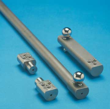
How do you calibrate and do interim evaluations of portable or articulating arm C.M.M.’s? There are two basic approaches to this challenge. Conventional very long Ball Bars (Dumbbells) may be used, with a conical cup or a three ball Kinematic coupling used in place of a probe sphere. Another popular approach is to reverse the design and build the Ball Bar (Dumbbell) with three ball Kinematic couplings in place of the spheres and using a large diameter spherical probe tip, to register in each of these three ball couplings. This device is called the Ball Bar Ranger™.
Laser Tracker Calibration
How do you evaluate the accuracy and repeatability of a Laser tracking device? By using the Ball Bar principles on a giant scale, but substituting a magnetically preloaded, three ball Kinematic mount for the balls, a standard spherically mounted corner cube can be moved from one, three ball Kinematic coupling to the next coupling, to provide a Ball Bar (Dumbbell) accurate evaluation of the entire Laser Tracker system. A first surface turning mirror to redirect the laser beam will reduce the size of the room required for this complete calibration.
More Information
For more information, see our page "All Ball Bars."