Bal-tec™ Home The Secrets of Ball Bar Calibration
The Secrets of Ball Bar Calibration
There are four basic qualities that comprise a full Ball Bar calibration. The first is to measure the sphericity of two balls. The second is the verification of the common spherical diameters of the two balls. The third is to measure the absolute diameter of the two balls, which is usually measured,, although this information has little practical application. The fourth is the ball center to ball center length of the Ball Bar.
For any calibration of a Ball Bar to be meaningful there are some fundamental design features that must be present. The roundness of the spheres must be laboratory quality (see A.N.S.I. B89.4.1-1997) and both of the balls must be exactly the same diameter. If an artifact is calibrated to an excellent level of accuracy, but it does not have long-term dimensional stability, the calibration will be rather meaningless, unless it is to be used in the next few days. In order to have the proper stiffness and thermal coefficient of expansion, the master spheres used on a quality ball bar will be made of a very high alloy stainless steel that is hardened. In our experience, the higher the alloy of a Martensetic (hard condition) steel the more difficult it is to dimensionally stabilize it. For this reason, it should be verified that the balls have received proper thermal stabilization treatment.
If the Ball Bar that we are calibrating was assembled with an adhesive that remains elastic, a whole list of unpredictable variables will exist so it is imperative that the proper bonding material and curing techniques were used. When in service the Ball Bar must be rigidly supported without changing its overall characteristics. These same requirements also apply when the Ball Bar is being calibrated.
Ball Sphericity
There are several factors such as the basic geometry of the ball seat and the shrinkage of the adhesive that can drastically change the sphericity of the balls after they have been mounted. So this measurement must be made after the Ball Bar has been assembled. Measuring the sphericity of the two balls after they are permanently mounted on the Ball Bar can be a real challenge.
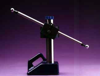
If a measuring machine like the Talyrond with a rotating measuring probe is available; it will only require a rigid holding fixture to achieve the measurement (see Figure #1.). When using rotating table type measuring machines, there can be problems. If the Ball Bar is placed at a near horizontal angle on the rotating table, a long Ball Bar will swing a huge circle that is usually larger than most labs can accommodate. One option when using a rotating table type machine is to stand the Ball Bar up vertically. Some axis of rotation measuring machines can accommodate this kind of measurement with good accuracy. Most of these machines will have a little cushiness, that may only be a micro inch at the tabletop but can grow larger every inch above the table until it amounts to a very substantial error at 20-30 or 40 inches (500-800 or 1000 mm) up in the air. When the Ball Bar is mounted vertically, orthogonal measurements of the balls roundness can not be made (see our paper "How Balls are Made How they are Measured and How they are Used in Metrology") so only a series of elevational evaluations can be performed. Although this measurement is a fairly safe bet, the sphere could actually be substantially elliptical or cylindrical or some other on axis figure and still look good along the axis of rotation.
In a last ditch approach, the sphericity of the balls can be evaluated by carefully rotating each of the Ball Bar Spheres in a Kinematic coupling while they are in contact with the measuring tip of a sensitive electronic probe. While this may sound like a worthless exercise, a very similar technique is specified by ANSI as a method for evaluating the Sphericity of precision bearing balls (see book #10 of A.N.S.I B3.12). In practice, one of our three ball Kinematic platforms, equipped with tungsten carbide balls and one of our two cylinder Kinematic Platforms are placed on the flat surface of a good granite table. An adjustable magnetic preload in the center of the three ball coupling will help to stabilize the readings and a drop of 3 in 1 oil® will keep from marking the ball. The bases for these Kinematic couplings are an extremely rugged four-inch diameter by one and one half inch thick steel platform. The base of the platform, which sits on the granite plate, has a precision flat lapped annular ring around the outside, so that there will be no wobbling during the measuring process (see Figure #2.). To meet the A.N.S.I. specification the two balls must be spherical within less than 5 micro-inches ( .000127 mm ).
Ball Diameter
The absolute diameter of the two balls on the ends of the Ball Bar are technically of little importance, but their common size is of extreme consequence. The sensitivity and repeatability of the measuring gage used to measure the size and common size of the two balls on the ball bar should be fifty nanometers - two micro-inches (0.000002 inch) or finer. Please refer to our paper "Measuring Absolute Ball Diameter Commercially." To meet the A.N.S.I. specification the two balls must also be a common diameter within 5 micro-inches ( .000127 mm ).
Ball Center to Ball Center Calibration Using a Standard Horizontal Measuring Machine
Although an accurate knowledge of the ball center to ball center dimensions not required to perform the ANSI-B89.4.1- 1997 volumetric evaluation, it is very valuable to have a long physical standard to tie down the C.M.M.'s dimensional accuracy. Several Ball Bars of different lengths can form an inexpensive way to evaluate the accuracy of the three scales and it will also give valuable information on the temperature effect of the environment on the machines performance.
The very complex problem of determining absolute ball diameter (see our paper "Measuring Absolute Ball Diameter Commercially") is further complicated by the fact that the linear measuring machine will have a very different force applied to the balls than the ball diameter-measuring machine. For this reason, the Hertzine Elastic Deformation will be different, therefore the measured length will be in substantial error. Fortunately, there is a measuring procedure that entirely eliminates the importance of an absolute knowledge of the balls diameter. After the common size of the two balls has been i validated, one of the balls is set between the flat parallel faces of the measuring machine anvils. For this measurement, the Ball Bar axis will be at right angles to the axis of the measuring machine. Using the size of this ball as a master set the horizontal measuring machine to zero. Next, open the moveable member of the machine to accommodate the Ball Bar. Set your support points about 20 percent in from each end and measure the distance between the ends of the two balls.
The beauty of this procedure can be appreciated by a simple analysis of the measurement. The distance the measuring anvil is moved from the measurement of the ball to the measurement over the two balls on the ends of the Ball Bar is exactly the ball center to the ball center dimension of the Ball Bar. By setting the machine to zero on the first ball we are in effect subtracting one half of the ball diameter from each end. The wonderful feature of this procedure is that there are absolutely no elastic compensations to be made. The forces applied to the original measurement of the master ball diameter are exactly the same as those applied to the two opposite ends of the Ball Bar's spheres. The material of the two balls is exactly the same so there will be no variation in the elastic strain imposed on the two surfaces of the single ball than on the two surfaces of the two balls on the opposite ends of the Ball Bar.
Compression of the Bar itself by the gaging force will be of no consequence as it is on the order of four or five nanometers, that is, a few tenths of one millionth of an inch maximum.