Bal-tec™ Home Ball Mounting For Kinematic Clamping
Ball Mounting For Kinematic Clamping
A Technical Paper & mdash; Mounting a Complete Ball
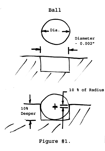
You can press fit a complete ball into a shallow counterbore. The diameter of the counterbore should be 0.002 inches (0.051mm) smaller than the diameter of the ball and about 10% deeper than the radius of the ball. To reduce the freeboard and improve the reliability of this design, a ball with a flat surface ground on it may be used. This design requires precise machining and is not the most reliable mounting method. It is too easy to pop a ball out of the shallow press fit. (See Figure #1.)
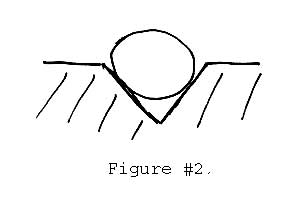
A complete ball can be glued into a conical pocket in the platform. We have experimented with every conical angle and configuration possible, and have never found one conical design that we consider satisfactory. With all of its limitations, there are situations where mounting the balls in conical recesses is the ideal solution. This is the typical situation in high vacuum and inert gaseous environments, where epoxy glue or other holding compounds are forbidden. The technique for achieving absolute dimensional stability between the ball and the conical cup is to generate a narrow spherical band, all the way around the conical cup, at the level of tangent contact with the ball. This narrow, high quality, spherical land can be easily generated by lapping with a diamond charged brass ball mounted on a cylindrical stem (see these devices on our web site). Using this approach, the ball is held in place by a threaded fastener. (See Figure #2.)
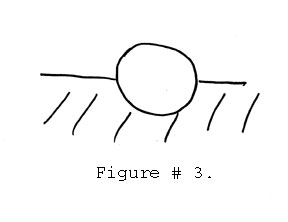
What works very well is to glue the balls into a well-formed hemispherical pocket in the platform. (See Figure #3.) This technique can be enhanced by using balls that have had part of the surface roughed up to provide a stronger glue line.
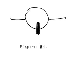
A big improvement over a simple ball glued into a pocket, is a ball with a blind hole, glued into a spherical pocket with a pin in the center. (See Figure #4.)
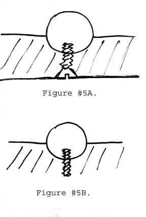
The ultimate design for a ball glued into a spherical pocket is to use a glued-in threaded ball held securely into the pocket with a threaded fastener from the back. (See Figure #5A & #5B.) This technique works very well when very close “Z” axis tolerance must be held. The depths of the three spherical pockets can be held within tenths of thousandths of an inch with relative ease, and when the balls are glued in the pockets using a heavy preload during curing, this quality will be maintained in the finished assembly.
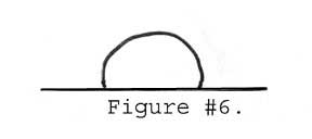
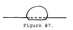
Cost may be a dirty word, but the economics of the design ends up being the driving force for every application. An effective and very economical design is to just glue truncated balls on the surface of the platform. Platforms of this design are very vulnerable to the balls shearing off due to a slight shock from the side. (See Figure #6.) This can be mollified by gluing the truncated balls into shallow, close fitting counterbores in the top surface of the platform. (See Figure #7.)
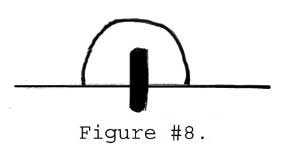
An even better design that is still inexpensive is to glue a truncated and counterbored ball with a blind hole to the flat surface of the platform over a pin. (See Figure #8.)
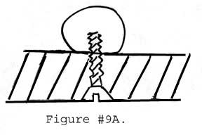
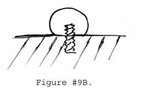
By far the most popular design is to use a truncated and threaded ball, held onto the platform by a threaded fastener from behind. (See Figure #9A & #9B.)
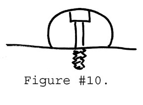
Another excellent approach is to use a truncated ball with a through hole and a counterbore in top to hold the ball, down from the front, with a socket head cap screw. (See Figure #10.) This is not our favorite design, as the top edge of the counterbore can scratch the mating kinematical components when the two misaligned platforms come into physical contact. Both of these foregoing designs are more costly.
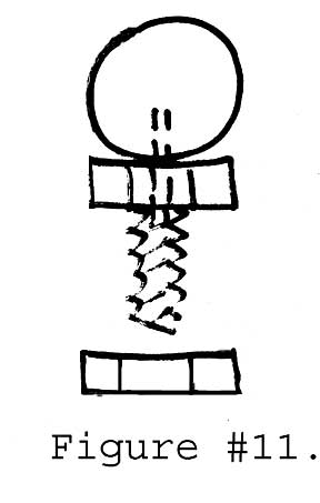
The “Address Sphere ™” was originally developed for precisely locating the position of tooling and inspection fixtures, but the concept lends itself to use in kinematical couplings. In this concept the ball is pinned and glued to the head of a stainless steel “Hex Head Cap Screw”.
These ball assemblies are mounted by simply drilling and taping the appropriate thread in the desired locations on the kinematical platform and screwing the parts in. This approach has the additional advantage that the “Z” axis is adjustable. The elevation, as well as the level, can be adjusted. Special designs can be custom fabricated with heavily truncated balls and thinned lock nuts to reduce the freeboard to a minimum. (See Figure #11.)
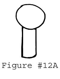
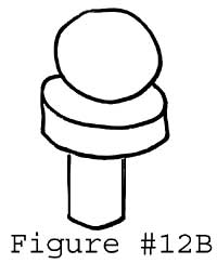
Another approach uses the tooling ball concept. Here a ball is mounted rigidly to a straight, cylindrical post, that is held to a close dimensional tolerance. The locating holes in the platform are drilled and reamed and the tooling balls are press or shrunk fit in place. These devices frequently have a flange adjacent to the ball, with a closely controlled dimension from the bottom of the flange to the centerline of the ball.
Commercially available tooling balls “suck”. Please excuse my colloquialism, but these devices are really bad. They are made with low grade commercial steel balls that have a hole drilled in them and are then press fit onto a soft steel post, which drives them out of round.
These commercial steel balls will rust in a normal room environment and they will fret under even the most modest loads. The more sophisticated tooling balls used for kinematical applications should be at least a hardened stainless steel. Tungsten Carbide ( TC ) is preferred. (See Figure #12A & #12B.)