Bal-tec™ Home CMM fixture building components
CMM fixture building components
Location and Clamping System — C.M.M. Fixturing — Fixturing Components — Fixture Building System — Part Holding System
Part location and holding for C.M.M. measurement and light machining has never been so easy. There are generally two choices in fixture building hardware. There are the cheap and dirty drilled and tapped plates of aluminum, with screw machined supports and clamping and there are the excellent high quality European systems, that literally cost a fortune.
We think of our designs as somewhere in between these two extremes. Instead of elaborate cams and jig bored locating positions, like the Europeans, we use very conventional designs, but our locating components are heavy duty hard stainless steel parts that are precision ground for a lifetime of service and our clamping devices use the heavy duty CMM industry, standard M10-1.5 threads.
Our 1.5” (38.1mm) thick pallets are very heavy duty aircraft quality aluminum alloy that is heat treated for full strength and durability. The hold down design, includes both heavy duty tee slots and frequent one quarter inch twenty threaded holes. The duality of this system lends itself to the greatest possible versatility. In addition to the excellent location and clamping that this system provides. This adaption allows for the use of almost any design or manufacturer of clamping and location hardware.
We are not some Johnny come lately, as our fixture building product line, dates back to 1996, so we have had many years of development behind us. If our heavy duty components are not abused, they will function indefinitely. An added feature of our fixture building product line, is that our high quality, heavy duty, products can be used with the flimsy drilled pallets that you may already have, until you are ready to invest in our premium pallets. This is done, through the use, of our long dual threaded adapter screws!
These adapter screws have a short section of 1/4 inch twenty, male threads on one end, to match the threaded holes in the low cost drilled and taped aluminum fixture building plates and then they step up to the CMM industry standard M10-1.5 thread of our high quality location and clamping devices.
The Riser Blocks
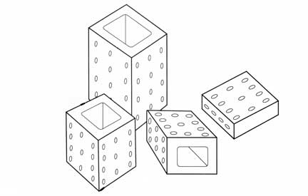
The standard four inch square Riser Blocks come in four different heights.
- The thinnest one (Part #10010) is four inches (10.2 cm) square by one inch (2.54 cm) thick. They are usually sold in sets of four pieces (Part #10020).
- The next thicker riser (Part #10030) is a four inch (10.2 cm) square by two inches (5.1 cm) thick. They are usually sold in sets of four pieces (Part #10040).
- The next thicker riser (Part #10050) is a four inch (10.2 cm) square by four inch (10.2 cm) forming a cube. They are usually sold in sets of four pieces (Part #10060).
- The longest or highest one (Part #10070) is four inches (10.2 cm) square by six inches (15.2 cm) long.
- They are usually sold in sets of four pieces (Part #10080).
- All of the Risers are manufactured from aircraft quality aluminum alloy for high strength and light weight.
- Large pockets are cored out on both sides of the thicker risers. This greatly reduces the weight while preserving a very rigid structure.
- All Risers have a well distributed group of M10 X 1.5 threaded holes on three faces. Any of our M10 threaded fixture building components are directly compatible with all Risers. Any of our components using the high load carrying one half inch (1.3 cm) diameter joint are made compatible with the Risers by using the One Half Inch (1.3 cm) Diameter Counter-Bored Adaptor (Part #20010). This device has an M10 X 1.5 threaded hole on one side and a one half inch (1.3 cm) diameter counter-bore, with a #10-32 clamp down thread in the center of the bottom.
- The Risers can be solidly clamped to the C.M.M. table or pallet by standard Bar-Hold-Down Clamps inserted into the cored-out sides or by using the Vee Bar-Hold-Down Clamps over M10 X 1.5 screws with a short cylinder.
- A very unique feature of these risers is the vacuum hold down chuck that is built right into their bases. When the table of the C.M.M. is a continuous high quality plane, such as granite, these vacuum chucks can be used to firmly clamp the risers in place. On a good flat surface this vacuum chuck will provide 94 pounds (42 kg) of holding force.
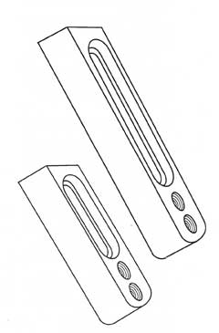
The Device Positioners
The Device Positioners are the mainstays of the modular fixture building system. They hold the location components and rigidly position them in exactly the right place on the Coordinate Measuring Machine table or pallet. They bridge the gaps between the threaded tie down inserts on Coordinate Measuring Machine tables or the distance between the Tee-Slots on the C.M.M. pallets.
In addition to their use as fixed location devices, they are easy to swing away after the test part has been clamped, to provide better measuring access. They come in two basic configurations. One or the other of these two designs will firmly hold every one of the location devices.
Two Location Points + A Clamp = Triple Packing Density
For higher packing density, the two vertical counter-bores and two M10 in the one end are spaced so that a short flat button and a longer cylindrical pin can both be mounted side by side. By resting the lower test part surface on top of the short flat button and the side of the port against the longer cylindrical pin, two degrees of test part freedom are restricted.
In addition a three quarter inch (1.9 cm) close clamp arm (Part #50260) can be installed on the longer cylindrical pin above the test part to act as a clamping device. The horizontal counter-bore in the end of the device is often used to hold a sphere or a flat button for low profile location. The end of the device postioners with the vertical location configurations are rounded off so that they will fit into more densely packed patterns.
The device positioners have a one inch (2.54 cm) square cross section and they come in three standard lengths. The shortest is four and one half inches (11.4 cm) long. The medium one is six inches (15.2 cm) long and the longest is eight inches (20.3 cm) long. Three pieces of each length and of each of the configuration comprise a full set of 18 device positioners (Part #40270). (see table for individual part numbers) These device positioners are machined from aircraft quality aluminum alloy. This high strength aluminum alloy is heat treated to develop maximum physical properties. The light weight of these aluminum parts is important because they are quite large and many of them are typically used on a single modular fixture.
These devices are usually held in place by an M10 socket head cap screw (Part #60120). This cap screw is located in a recessed channel machined down the length of the part. This design leaves the top surface of the positioner clear of any obstructions.
A special keyed washer (Part #70020) is used under this cap screw to prevent the cap screw's rotation from wearing the bottom surface of the recessed channel.
A "lock out pin" is installed in the socket head of these cap screws. This "lock out pin" requires the use of a special low torque wrench (Part #80030) which will prevent over tightening. Please note: A very special set of dual threaded adapter screws, (see C.M.M. Technical Data Sheet #14. Table #2.) are available to secure the Device Positioners to the table of any C.M.M. or to competitors pallet systems. The dual threaded adapters have a short threaded section on one end. This short section comes in a wide variety of thread sizes to match any machine table or pallet system. The other end has a one and one half inch (3.8 cm) long section of M10 X 1.5 thread. For this application our standard threaded hand knob (Part #80010), with a hardened steel washer (Part #70010), to prevent galling, is screwed down onto this longer threaded section to rigidly hold down the device positioner.The M 10 X 1.5 Threaded Device Positioners
The first design is used to hold those fixture building components that have M10 X 1.5 threads. They have two M10 X 1.5 threaded holes vertically through the thickness on one end of the positioner and one horizontally through the opposite end. In addition to their function as location positioning devices, these M10 threaded components make excellent screw clamping devices, for either vertical or horizontal applications. To use them as a screw clamping device, the proper length of M10 X1.5 Threaded Aluminum Stud is screwed through either the vertical or the horizontal threaded hole. A universal clamping tip (Part #50220) is attached to the contact end of the Threaded Aluminum Stud. An M10 X 1.5 coarse knurled Jam-Nut (Part #20050) can be finger tightened to lock the threaded stud in position. The height and position of this screw clamp is arranged by attaching it to other fixture building components.
Device Positioners — M 10 X 1.5 Threaded Design
| Part Number | Length |
|---|---|
| 40190 | 4 1/2" ( 11.4 cm ) |
| 40200 | 6" ( 15.2 cm ) |
| 40210 | 8" (20.3 cm) |
The ½ Inch Counter-Bore Device Positioners
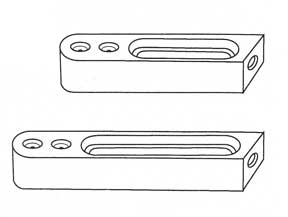
The second design is used to hold these location devices that have the heavy duty, one half inch (1.27 cm) diameter boss and a #10-32 hold down thread. At one end they have two, one half inch (1.27 cm) diameter vertical counter bores on the top face. There is a clearance hole for a #10-32 screw going through the center of the counter bores to tie down the mating device. Therc'ls a single horizontal one half inch (1.27 cm) diameter counter-bore in the opposite end. This counter bore has a #10-32 threaded hole in the bottom to tie down the location device.
| Part Number | Length |
|---|---|
| 40230 | 4 1/2" (11.4 cm) |
| 40240 | 6" (15.2 cm) |
| 40250 | 8" (20.3 cm) |
Nine Piece Set - 3 of each of 1/2" C.B. PART #40260 The Full 18 Piece Set of Device Positioners ( PART #40270 ) Consistes of 3 pieces of each Length and of each design
12" x 16" Kinematic Platform
The 12 inch by 16 inch (304 mm by 406 mm) Kinematic Platform is a well-established design with years of successful use. This seasoned design is rugged, but at the same time it is lightweight. A high stiffness is achieved through an integral ribbed structure. The cast aluminum design provides good damping and high stiffness. The top platform is one and one half inches (38 mm) thick but weighs only 16 pounds, (7.2 kg). The overall height from the bottom of the bottom platform to the top of the top platform is three and one quarter inches (3 1/4", 82.6 mm).
The Kinematic couplings used on this platform are of a high load carrying design. It uses three spheres of three quarter inch ( 3/4", 19mm) diameter on the bottom and three cylindrical vee's on the upper plate. The three spheres are not ordinary steel bearing balls; but are ultra fine grain, high chrome, high carbon stainless steel that is hardened to 58 HRC minimum and precision lapped to AFBMA instrument quality grade 10. Standard steel bearing balls used in competitive products are prone to rust and are very susceptible to fretting, which is one of the major problems of Kinematic couplings.
The Kinematic couplings in the top platform consist of three pair of one-half inch (1/2", 12.7 mm) diameter cylinders that form three vees. These cylinders are securely glued into three precision-machined trenches, with a ceramic filled epoxy, that has a 3000-pound per square inch (535 kg per square cm) shear strength. These cylinders are made of exactly the same material and processed in the same manner as the precision balls. After hardening, these cylinders are ground and precision lapped to a surface texture that is below one microinch (25 nm) Ra. This contrasts with competitive products that use commercially ground only dowel pins, made of carbon steel that is prone to rust and very susceptible to fretting.
There are two standard versions of the 12"-16" top platforms. It is available with a plain flat top surface, so that our customer can provide any custom mounting facilities they desire; or we will bid machining the mounting features to your blue print or rough sketch. The top surface of this platform is ground flat. This plain configuration is the least expensive. It is part number KP-12-16-P.
Top Platform
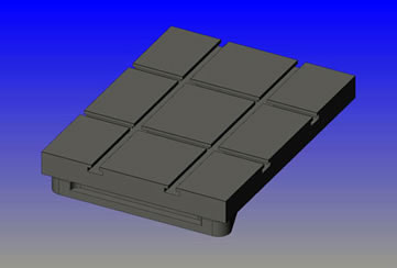
The top platform is also available in our standard breadboard configuration with four precision machined tee slots that use standard three eighths of an inch (3/8") or M10 Tee-nut hardware. This arrangement allows an infinite variety of mounting configurations. The top surface of this platform is ground flat. This is part number KP-12-16-S.
| Downloads | ||
|---|---|---|
| Solidworks | IGES | |
| N/A | ||
Bottom Kinematic Platform
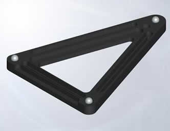
There are also two standard versions of the bottom platform. The first version of the bottom platform is built in a rugged triangular configuration. There are three slots that run the length of each leg of the triangle, that will accept either three eighths of an inch or M10 socket head cap screws, for holding this platform to its mounting surface. There is also a recessed ridge around the inside and outside rim of the triangle that will facilitate the use of hold down clamping.
The second standard version of the bottom platform consists of three separate, one and one half inch (1 1/2", 38 mm) wide, by one inch (1", 25.4 mm) thick, by five-inches (5", 127 mm) long bars. Each bar has an instrument quality, grade 10, sphere rigidly mounted on one end and a four inch long recessed slot, that will accept a three eighths of an inch or M10 socket head cap screw to hold it down. This set of 3 pieces is part KP-3-BAR. With a symmetrical light load, the 12-16 platform can repeat in all six degrees of freedom within 4 microinches (0.1 micrometers). This platform will carry up to 100 pounds (45 kg) of load safely.
| Downloads | ||
|---|---|---|
| Solidworks | IGES | |
Mechanical Hold-Down
The substantial weight of the top platform, at 16 pounds (7.2 kg), usually precludes the need for additional preload; there are, however, circumstances that do require it.
Vertical Mounting
With its very rugged construction this platform lends itself to vertical or even upside down mounting. The facility for mechanical pre loading is built right into the design of the 12-16 Kinematic platform. A special version of the three quarter inch (3/4", 19 mm) diameter spheres used in both versions of the bottom platforms can have a one-quarter inch (1/4", 6.4 mm) diameter clearance hole drilled through them. The three quarter inch (3/4", 19 mm) diameter Kinematic sphere with clearance hole drilled through it is (our part number 75-270-CH). Three of these
Then a one-quarter inch (1/4", 6.3 mm) by 20-threaded hole is drilled and tapped below these spheres. There is a one quarter inch (1/4", 6.3 mm) diameter clearance hole drilled through the top Kinematic platform that allows a piece of continuous threaded stock to screw into the bottom platform and pass up through the top platform.
When mechanical clamping is used, it is important to isolate all of the potential X-Y and Z axial errors to prevent any cocking tendencies when the clamping force is applied. This is done by incorporating a spherical tilt between the clamping force and the top of the platform. This spherical tilt is (our part number 75-ST-270). The full mechanical clamp requires three
The clamping force to hold the two platforms together is provided by three, one-inch (1", 25.4 mm) diameter knurled clocking nuts, (part number 250-20-CN). These clocking nuts include a ball thrust bearing that decouples the torque generated by tightening these nuts. A wing nut and washer are supplied to be used as a jam nut, under conditions of moderate
The clocking nut is a one-inch (1", 25.4 mm) diameter knurled, stainless steel device, with a clocking line engraved on the top face, so that the clamping force generated by tightening it can be repeated time after time. This clamping force will have a major effect on the "Z" axis position as well as the pitch and roll of the top platform.
Note: If mechanical clamping is going to be required, it must be ordered at the time the platform is purchased.
Spring Loading
Spring-loaded clamping may be desirable in some applications. When this option is used, it is only necessary to add springs of the proper rate and washers between the clocking nuts and the spherical tilts or between spherical tilt and the platform. A 12-16 Kinematic platform that is provided with mechanical clamping can be converted back to a simple platform by just unscrewing the three pieces of 1/4-20 continuous threaded stock.
The complete mechanical clamping kit, with all three sets of components, installed on the platform is part number 12-16-FS-KIT-750. Additional information on mechanical clamping of Kinematic couplings may be found in the addendum to our Kinematic Catalog 105B.
Custom Versions
Other features, such as hard anodize, nickel plated surfaces, or precision flat lapped reference surfaces can be supplied on special order. This Kinematic platform can be supplied with cemented tungsten carbide component parts that will give higher load carrying capacity, a higher resonate frequency and much better repeatability. The top platform can also be supplied with a pattern of drilled and tapped holes of either English or metric diameter to suite the customer's requirements.
The Double Adjustable Screw Stop Post
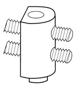
This device (Part #40300) has two horizontal M10 X 1.5 threaded holes threaded through the one and one eighth inch ( 1 1/8", 1.125", 2.9 cm ) diameter body of the part. The lower M10 X 1.5 screw is three quarters of an inch ( 3/4", 0.75", 1.9 cm ) above the base and the upper one is one and five eighths of an inch ( 1 5/8", 1.625", 4.12 cm) above the base. The overall height of the device is two inches ( 2.0", 5 cm) tall. The Double Adjustable Screw Stop Post comes in six piece sets (Part #40310).
A two inch ( 2.0", 5 cm) long adjustable stop screw (Part #60150) is provided. It has an accurately machined spherical end. This screw is supplied
with a course knurled Jam-Nut (Part #20050), so that the final settings can be locked in place by hand tightening.
These spherical ended screws find many other applications with components such as the Precision Jacks, Bar-Hold-Down Clamps and Cylindrical Risers. Extra screws (Part #60150) and Jam Nuts (Part #20050) can be purchased separately.
The post is located by our standard one half inch (1/2", 0.5", 1.27 cm) diameter precision boss and is held in place with a #10-32 socket head cap screw. In addition to its use as a precision stop, the Double Adjustable Post makes an excellent clamping device.
The Short Adjustable Screw Stop Post
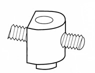
The Short Screw Stop Post (Part #40280) has a single horizontal M10 X 1.5 threaded hole through the one and one eighth inch (1 1/8", 1.125", 2.9 cm) diameter body. This M10 X 1.5 threaded hole is three quarters of an inch (3/4", 0.75", 19.5 cm) above the base. This device is one and one quarter inch ( 1 1/4", 1.25", 3.2 cm ) tall. The Short Adjustable Screw Stop Posts come in six piece sets (Part #40290). A two inch (5 cm) long adjustable stop screw (Part #60150) is provided.
It has an accurately machined spherical end. The screw is provided with a coarse knurled Jam-Nut (Part #20050) so the final setting can be locked in place by hand tightening. The post is located by our standard one half inch ( 1/2", 0.5", 1.27 cm ) diameter precision boss and is held in place by a #10-32 socket head cap screw. In addition to its use as a precision stop, the Short Adjustable Post makes an excellent clamping device.
The Extension Nuts
The standard extension nut is (Part #20030). They are usually sold in sets of six pieces (Part #20040).
There are two common applications for these extension nuts. The first is to lengthen the standard M10 X 1.5 threaded stud. For this application, the nut is screwed onto the first stud about one half of its length. The second threaded stud is screwed into the nut until it touches the first stud and it is tightened.
The second common application is to adapt the various thread sizes in different C.M.M. tables or other manufacturer's pallet systems to Bal-tec's standard M10 X 1.5 thread. This is done by screwing a short dual threaded adaptor screw of the proper thread size into the C.M.M. table or pallet and then screwing the extension nut onto the M10 X 1.5 end of this dual adaptor screw. This leaves an M10 X 1.5 female thread for adapting any of our fixture building devices.
In addition to the common applications, these extension nuts also make very compact light duty jacks. One of the various lengths of M10 X 1.5 threaded aluminum studs is simply screwed into the top of the extension nut and a knurled M10 X 1.5 jam nut (Part #20050) is used to fix the elevation.
This one and one-half inch ( 1 1/2", 1.50", 3.8 cm) long extension nut is one and one quarter inch ( 1 1/4", 1.25", 3.1 cm) in diameter. It has a coarse knurl on the outside diameter so that no tools are required for its use. These 18-8 alloy stainless steel nuts will not rust.
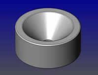
Female and Male Cones
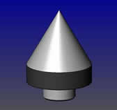
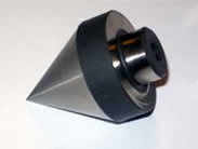
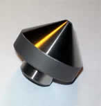
When the surface of a Male Cone is brought into contact with the circle formed at the intersection of a hole and a plane, three degrees of test part freedom are constrained. Two side by side Cones will form an excellent Vee Block to restrict two degrees of test part freedom. The smallest Male Cone (Part #CO-M-60-CPM ) has a 60 degree included angle, so that it is compatible with the standard shaft centers. It starts at a sharp point and goes up to one inch ( 2.54 cm ) diameter. This small Cone is made of hardened stainless steel and the Cone is precision ground.
This smallest of the conical component uses the standard one-half inch (1.27cm) diameter boss with a #10-32 hold down thread to form a high load carrying joint. Another small diameter hardened stainless steel Male Cone, ( Part #CO-M-90-CPM ) has a 90 degree included angle. The 90 degree angle starts at a one-eighth inch ( 0.125", 0.32 cm) diameter flat tip and goes up to the full one inch ( 2.54 cm ) diameter. This Male Cone is precision ground. It has the standard one-half inch (0.50", 1.27cm) diameter boss ( post ) with a #10-32 hold down to provide high load carrying capacity.
| Downloads | |||
|---|---|---|---|
| Part # | Solidworks | IGES | |
| CO-M-60-CPM | |||
| CO-M-90-CPM | |||
| Downloads | |||
|---|---|---|---|
| Part # | Solidworks | IGES | |
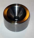
| CO-F-SM | |||
| CO-F-CPM | |||
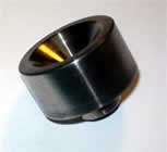
The three larger Cones are made of aircraft quality high strength aluminum alloy that is hard surfaced for wear resistance. The smallest Aluminum Cone (Part #40030) starts at five eighths of an inch (1.6 cm) diameter and goes up to one and three quarters inch (4.5 cm) diameter. It is three quarters of an inch (1.9 cm) thick.
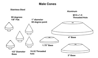
The next larger Aluminum Cone (Part #40040) starts at one and one half inch (3.8 cm) diameter and goes up to three inches (7.6 cm) diameter. It is seven eighths of an inch (2.2 cm) thick. The largest of the Aluminum Code ( Part #40050) starts at two and one half inches (6.35 cm) diameter and goes up to four inches (10.2 cm) in diameter. It is one inches (2.54 cm) thick.
These larger Aluminum Cones have a 90 degree included angle for long wear and good load carrying capacity. It should be noted that there is a small overlap between the individual diameters of the Cones so that there is no chance of a gap in the hole sizes that can be accommodated.
The three larger Male Cones have an M10 X 1.5 threaded hole all the way through the center of the part to provide for solid attachment to the mating fixture building component.
The remaining cylindrical diameter at the bottom of these Cones can be used as a cylindrical location datum. When any one of these Aluminum Cones is turned up side down they provide an excellent flat location table. The four inch (10.2 cm) diameter Cone has two additional M10 X 1.5 threaded holes in the flat location table. The four inch ( 4.0", 10.2 cm ) diameter Cone has two additional M10 X 1.5 threaded holes in the flat back side to provide extra utility for location and clamping.
The Finger Knob
The Finger Knob (Part #50340) is 3/4 inch (0.75", 1.9 cm) diameter by two inches ( 2.0", 5.1 cm) long. It is usually sold in 6 piece sets (Part #50350), The entire two inch (5.1 cm) length of the part has a coarse straight knurl to provide maximum gripping. It is drilled and threaded for an M10 X 1.5 thread. This finger knob is used to rotate threaded aluminum studs for clamping applications. It is provided with a short M10 X 1.5 set screw (Part#60140) that can be used behind the threaded aluminum stud to lock it into the knob. The finger knob is made of aircraft quality aluminum alloy for high strength and light weight.
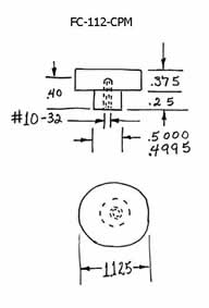
The Half Inch Counter Bored Adaptor
The one half inch (1.3 cm) counter bored adaptor is (Part #20010). They are usually sold in sets of six pieces (Part #20020).
Any of the components using the high load carrying, one half inch (1.3 cm) diameter joint are made compatible with M10X1.5 threads through this one half inch counter bored adaptor. This device has an M10 X 1.5 threaded hole on one side and a one half inch (1.3 cm) diameter counterbore, with a #10-32 clamp down thread in the bottom of the other.
The counter-bored adaptor is solidly clamped to the other fixture building devices through the M10 X 1.5 threaded hole on the back side. It has a coarse knurl on the top half of the outside diameter so it can be rigidly clamped to the mating part by hand tightening. The adaptor is one and one eighth of an inch ( 1 1/8", 1.125", 2.9 cm) in diameter and one inch (2.54 cm) tall. It is made of type 18-8 alloy stainless steel, so it will not rust.
The Heel Cup
The Heel-Cup (Part #50240) is used to establish the rough height of the Bar- Hold-Down Clamp. The Heel-Cups come in eight piece sets (Part #50250). There is a shallow recess in the top of this cup. It is used to keep the head of the leveling screw in the Bar-Hold- Down Clamp centered. There is an M10 X 1.5 threaded hole, one half of an inch (1.27) cm) deep in the center of the cup's lower surface. This female thread is used to adapt the cup to cylindrical risers and other fixture building devices.
A short M10 X 1.5 coupling screw ( Part #60140) is supplied with each Heel-Cup. It has a coarse knurl on the one and three sixteenths of an inch ( 1 3/16", 1.1875", 3 cm) outside diameter. This coarse knurl allows the devices to be installed on its mating component by hand tightening. This low profile cup is only six hundred and fifty thousandths of an inch ( 0.650", 1.65 cm ) thick. The Heel-Cup is manufactured from aircraft quality aluminum for light weight and high strength.
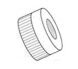
The Knurled Jam-Nut
The Knurled Jam-Nut (Part #20050) is the universal locking device for all M10 X 1.5 components. They are available in ten piece sets (Part #20060). They are one and three sixteenths-inch diameter (1 3/16", 1.1875", 30.1625 mm) and three-hundred-thousandths of an inch thick (0.300", 0.76 cm). They feature a course knurl on the outside diameter to facilitate hand locking.
Made of type 18-8 stainless steel, they will never rust.
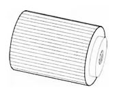
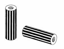
The Round Extensions
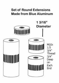
A full 16 piece set of Round Extensions (Part #30090) consists of four each of the one inch ( 1.0", 2.54 cm ) high ( Part #30050), the two inch ( 2.0", 5.1 cm ) high ( Part #30050), the three inch ( 3.0", 7.6 cm ) high (Part #30070), and the six inch ( 6.0", 15.2 cm ) high ( Part #30080 ) extensions. These extensions are designed to increase the length of the Precision Jacks, and the Heal Cups for Bar-Hold-Down Clamps. The four sizes allow the height of these devices to be increased in one inch increments.
These same extensions work well as general purpose extension platforms for any location device. They have a course knurl on the outside diameter, so that they can be tightened down and removed by hand. The round extensions are one and three sixteenth inch ( 1 3/16", 1.1875", 3 cm ) in diameter, and they have a one inch ( 1.0", 2.54 cm ) deep hole with a M10 X 1.5 thread three quarter inch deep ( 3/4", 0.75", 1.9 cm ) into the center or each end. The round extensions are machined from aircraft quality aluminum alloy for high strength and light weight. Note that these Round Extensions can be adapted directly to any C.M.M. table or pallet systems through a set of Dual Threaded Adaptor Screws.
Plain Flat Kinematic Component
For many years past the trend in kinematic coupling designs has shunned the classical Conical Cup, Vee Block and flat plane as described by both Maxwell and Lord Kelvin in separate publications in the late eighteen hundreds. This reluctance was based on the great difficulty of generating very high quality Conical and Vee Block surfaces.
Standardized kinematic components are now available that solve these age old quality limitations. Availability of these components has rekindled interest in the classical designs with the many advantages that are offered by the diverse components. An outstanding example of these advantages is the ability of an axis to pivot with unheard of accuracy along the line axis between the Conical Cup and the Vee Block.
Among the kinematic purists out there, this will end up as a button pushing opportunity. If the Vee Block is pointed at the bisector of the kinematic axis of the coupling, the line axis of the pivot could undulate because the two tangent contacts are not on the pivot axis. If on the other hand, the Vee Block is pointed parallel to the axis, we want to depict that we are no longer in strict compliance with kinematic principles.
If there is one thing that we have learned through the years, is that kinematics in general are very forgiving. A line of standardized flat components are available to go along with the conical cups and the more sophisticated components like the Rose Bud and Prismatic Components. The design of the first of the standard flat devices is for everyday applications. It is a disk made of micro "grained" stainless steel that is hardened to 58 HRC minimum. These disks are ground parallel and the working surface is lapped flat with a 2 microinch (.05 micrometer) Ra surface quality. There is a blind threaded hole in the back surface to hold them on the Kinematic Platform.
Standard Flat Components
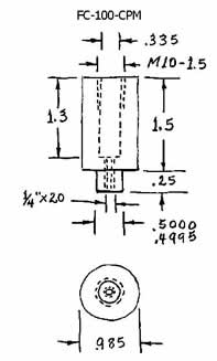
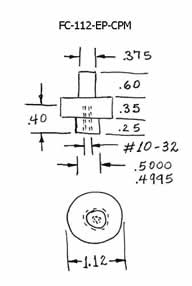
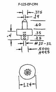
The Giant Two Inch Diameter Flat
- This very large, very rugged, flat, kinematic component, is offered in both the surface mount and the cylindrical post mount designs. The surface mount design is our part number F-2000-SM.
- The major cylindrical diameter of this giant part is 2.00 inches (50.8 mm).
- The body of this part is 5/8 inch ( 0.625", 15.88 mm) thick.
- It has a one half inch (0.50 inch) [12.7 mm] diameter national fine (20 threads per inch) threaded hole in the center of the back of the part that is used to hold the part in position.
- The depth of this thread is 0.380 inch (9.65 mm).
- There is a 1.00 inch [25.4 mm] diameter shallow counter bore in the center of the back surface of this part that is 0.04 inch [1.0 mm] deep.
- Additional holes, threads, or slots, can be Electrical Discharge Machined ( EDM ), to specific customer requirements. See Figure #1.
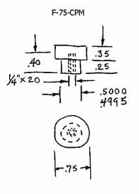
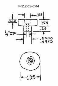
- The cylindrical post mounted version of this giant flat component is our part number F-2000-CPM.
- The major cylindrical diameter of this part is 2.00 inches (50.8mm).
- The body of the part is 5/8” 0.625 inch (15.88 mm) thick.
- The diameter of the cylindrical post is cylindrically ground to 3/4" 0.750inch (19.05 mm) plus nothing, minus 0.0005 inch (0.0127 mm).
- The cylindrical post is 1/2” 0.500 inches (12.7 mm) long.
- There is a 3/8” 0.375 inch(9.5 mm) diameter with a 16 TPI threaded blind hole in the center of the post that is 1/2" 0.50 inch (12.7 mm) deep. This threaded hole is used to hold the part in place.
- The flat flange between the 3/4" 0.75 inch (19.05 mm) cylindrical post and the 2.00 inch (50.8 mm ) major diameter, is precision ground flat and square to the post within 0.0002 inch (0.005 mm). See Figure #2.
- These large flat parts are made of a Martensitic stainless steel that is hardened to 58HRC.
- This very fine grain material has a very high tensile strength of 285,000 P.S.I.
- The flat working surface of these parts is precision ground parallel to the back flange and lapped flat.
- In addition to their use as a high load carrying kinematic component, this device makes an excellent anvil for dimensional metrology or as a flat reference datum for optical bread boards.
Standard Flat Components - Pricing
| Part # | Description | Price | Purchase |
|---|---|---|---|
| CO-60-CPM | CONE, MALE, 60°, 1" DIAMETER, STAINLESS STEEL | $52.80 | |
| CO-90-CPM | CONE, MALE, 90°, 1" DIAMETER, STAINLESS STEEL | $52.80 | |
| CO-F-CPM | CONE, FEMALE 1.125" ( 1 1/8", 28.575 MM ) DIAMETER, CYLINDRICAL POST MOUNT, STAINLESS STEEL | $52.80 | |
| CO-F-SM | CONE, FEMALE 1.125" ( 1 1/8", 28.575 MM )DIAMETER, SURFACE MOUNT, STAINLESS STEEL | $52.80 | |
Special Order Only
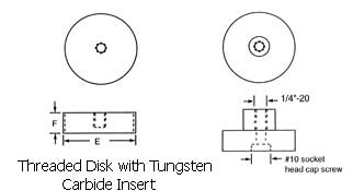
We will custom manufacturer any special design required to fill specific customer needs for corrosion resistance and magnetic or electrical properties. The third option has the same design features as the standard flat devices except it has a precision ground cylindrical boss that provides excellent locate-ability.
For premium applications, there is a steel disk that is threaded on the outside diameter. There is a smaller tungsten carbide disk glued in the center of the working face. This carbide disk is lapped flat with 1 microinch (.025 micrometer) Ra surface quality. Tungsten Carbide is the stiffest, hardest, commercially available material, with a Young's Modulus of Elasticity of 98,000,000 PSI and a hardness of 91 HRA. This thread on the disk can be used as an adjustment or to lock the device in place. As an alternative, it can simply be permanently glued into an oversize counterbore. There are four holes drilled in the top face. This allows adjustment up and down by rotating it with a special Spanner Wrench, Part Number SW -1.
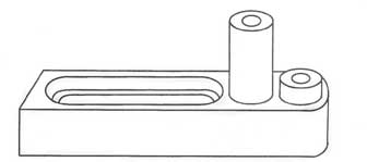
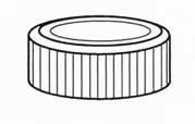
Clay Pots — Part-Clamping Devices — Clay-Clamping Devices — Part Holding Devices

The clay pots are an excellent way to hold very complex parts, especially ones that do not have nice square or flat reference surfaces to clamp them by. Select a clay pot that is large enough to hold the part to be measured. The flange of aluminum body of the clay pot is clamped down on the table top of the Coordinate Measuring Machine (C.M.M.), with standard bar clamps such as our 6” long clamp, part number 50030. The bases of the clay pots are precisely machined flat, so that when they are clamped down, they do not wobble even microinches.
The body of the part to be measured is simply pressed down into the clay, and the clay is kneaded tightly around all edges. Reference datums are first established by measuring them with the probe. The dimensions of the rest of the exposed part are then measured. After these measurements are complete, the part is pulled up out of the clay and relocated on approximately the opposite side. The reference datums are reestablished by probing them. The previously unmeasured surfaces of the part are surveyed and the inspection is complete. Any residue of the oil based clay can be easily removed with a detergent wash or solvent.
The clay pots are available in two standard sizes
- Part number CP-4
- is 4 inches (101.6mm) plus wide by 4 inches (101.6mm) plus long. It is 2 inches (50.8mm) deep.
- Part number CP-6
- is 6 inches (152.4mm) plus wide by 6 inches (152.4mm) plus long. It is 2 inches (50.8mm) deep.
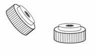
The Universal Tee-Nut
The Universal Tee-Nut ( Part Number 20070) fits all of our standard pallets, rails and fixture building frames. This Tee Nut is provided with two threaded holes. One threaded hole is a M10 x 1.5 and the other is a #10-32. One or the other of these two standard threads will fit our entire line of fixture building components. This robust Tee-Nut is one inch ( 2.5 cm ) long, one inch ( 2.5 cm ) wide and one half inch ( 1.3 cm ) thick.
The Universal Tee-Nut also comes in an eight piece set ( Part # 20080 ). For maximum weight reduction, the Tee-Nuts are manufactured from an extremely high tensile aluminum alloy that is stronger than mild steel.
Aluminum Vise for C.M.M. Use
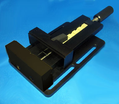
This very light weight vise is made from an aluminum alloy that is as strong as steel. This vise is our Part Number AL-VI-6. This strong, light weight vise is ideal for holding parts on coordinate measuring machines. The base of the Vise is 5" inches (127 mm) wide and 7.9" inches ( 200.7 mm) long. The top of this vise is 2" inches ( 50.8 mm ) above the base. The width of the standard jaws is 4" inch ( 101.6 mm ). The height of the standard jaws is 2" inch (50.8 mm). The jaws of this vise will open 4.345" inches (110.4 mm).
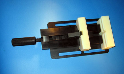
This vise weighs only 4.6 pounds ( 2.1 kg ). See left figure. The standard vise jaws are hard anodized for long trouble free use. The standard jaws have a horizontal and a vertical vee machined to provide accurate location for cylindrical parts. A set of replacement jaws made of Nylon Plastic are available for holding sensitive parts that might be marred by the standard hard anodized aluminum jaws. The Part number for these nylon jaws is NJ-6. See right figure.
A set of very tall replacement jaws are available. These jaws are 7 1/4 inches (184.15 mm) above the top surface of the vise. These jaws are 6 inches (152.4 mm) wide, to provide extra area for location. These taller, wider, jaws are made of raw aluminum to allow custom tailoring to hold specific parts. The Part number for these tall jaws is TJ-6.
A very special feature of this vise is the availability of a “pin” clamping system for routinely holding parts that would otherwise be difficult or impossible to hold in a standard vise. This feature consists of two replacement jaws that are much broader than the standard jaws. There is a pattern of drilled and threaded holes in the top surfaces of these broader jaws. The part that actually holds the part in place consists of threaded studs of various designs that can be screwed into these holes in the proper patterns to match features of the part, thus providing a fast accurate clamping method of securing the test part for measurement. This works as a Jewlers Jaw. The Part number for the pin jaw kit is PJ-6.
Standard raw aluminum jaws are available, that can be machined by the customer to accurately hold precision parts, without distorting them. These soft aluminum jaw blanks are part number AL-J-6. This vise can be supplied with a set of kinematic hardware, our part number KIN-VI-6, that allows it to be removed from the C.M.M. table and then it can be replaced back on the table, in exactly the same spot within micro-inches. A much smaller diameter pin that extends above the thread makes a version of this vise to go on a long narrow pallet. It basically consists of two jaws that attach to the long narrow pallet.
Pricing For CMM Vise
| Part # | Description | Price | Purchase |
|---|---|---|---|
| AL-VI-6 | CMM VISE | $204.00 | |
| TJ-6 | EXTRA LARGE JAWS FOR CMM VISE ( PAIR ) | $93.50 | |
| KIN-VI-6 | KINEMATIC LOCATION | $132.00 | |
| NJ-6 | NYLON JAWS FOR CMM VISE ( PAIR ) | $71.50 | |
| P-J-6 | PIN CLAMPING JAWS ( PAIR ) | $132.00 | |
| ALJ-6 | SOFT ALUMINUM EXTRA LARGE JAWS FOR CMM VISE ( PAIR ) | $71.50 | |