Bal-tec™ Home Kinematic Coupling Design for "Z" Axis Repeatability
Kinematic Coupling Design for "Z" Axis Repeatability
There are six individual points of physical contact in a fully constrained kinematic system. With this many variables, holding accurate X-Y-Z positional dimensions is challenging. Kinematic couplings, in a general sense, are not used to define specific dimensions, but rather to provide almost perfect repeatability of the removable platform in relation to the fixed base in all six degrees of freedom, and without any of the distortions caused by over constraint.
Building several kinematic clamping systems with identical “Z” axis elevations can be done quite simply. A typical application for this kinematic design would be to facilitate accurate repeatability in a multiple pallet system for photolithography. Developing an economically successful system of this type requires an open-minded acceptance of some unique ideas. In order to reverse the normal tactics and take full advantage of the basic fundamentals of geometry, this device must be built of component parts that are manufactured to extreme dimensional accuracies.
This is in contrast with conventional kinematic components that only require reasonable geometry and excellent surface quality. In order to achieve symmetry, the fundamental choice of design will be the Maxwell system. This configuration uses three vees and three spheres and will give excellent location and repeatability in all six degrees of freedom.
Using three pairs of exactly matched cylinders to form the three vees provides a design with component parts that can be economically produced to extreme dimensional accuracy. By separating each of the two cylinders with two very precise spacers, exactly matched sets of precision vees can be produced at a very modest cost.
We have found that the most accurate and the least expensive spacers are matching cylindrical disks. We basically cut perfectly square cylindrical disks from a ground and precision lapped, hard steel cylinder, so that the individual disks are matched within a few micro inches.
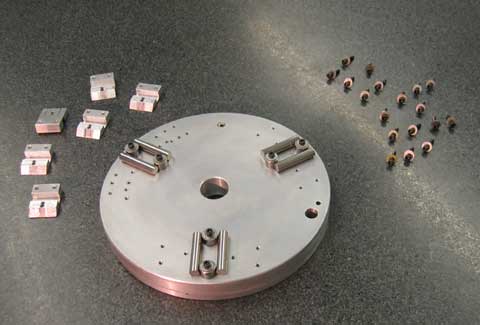
Three of these assembled devices can be clamped or clamped and glued in a 120-degree pattern, on a flat reference plane of the system. The kinematic nature of this placement makes both the angular and radial location of the assemblies very forgiving.
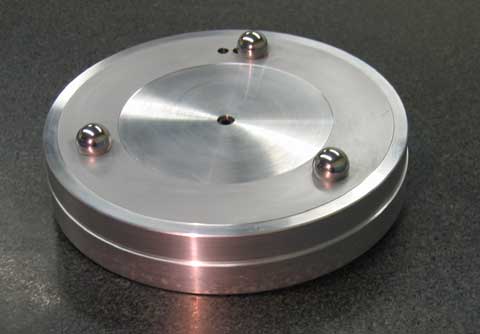
Locating three complete spheres in a mechanically stable manner is extremely difficult. Fortunately, the cost of producing groups of truncated spheres with a consistent dimension from the apex of the sphere to a flat annular base is modest. By adding a recess and a threaded hole in the flat base, we get a very dimensionally stable component that is easy to tie down. Here again the forgiving nature of the Maxwell system is to our advantage.
A good commercial choice of material for the kinematic components is a fine grain Martensitic stainless steel that will through harden to at least 58 HRC. A dramatic improvement in repeatability, load carrying capacity and stiffness can be achieved by building the component parts from Tungsten Carbide (TC). Unfortunately, the cost of producing these high-end components is at least four times that of the hard stainless steel.
The working surfaces of the component parts must be precision lapped to achieve the fine surface texture and excellent geometry that is needed to assure accurate repeatability. If the design can be adapted so that the flat annular base of the spheres can be attached directly to the object being located, the best possible system can be produced.
By relieving all of the flat mounting surfaces on the platforms to leave three flat pads, or at most an annular ring, it is economically feasible to flat lap these areas to produce microinch accurate datums to mount the kinematic components on.
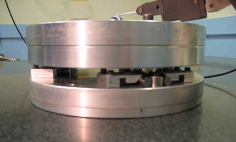
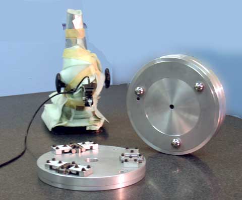
The test beds that are shown in the accompanying photos consistently repeated to less than 50 microinches (one micrometer). These kinematic assemblies can be dismantled, the components intermixed, reassembled repeatedly showing this high degree of accuracy.