Bal-tec™ Home The Whiffletree
The Whiffletree
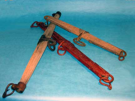
To whiffle is to change back and forth frequently. The Whiffletree, (also known as the swivelltree, single tree, wiffletree, wiffle tree and whippletree) dates back to the use of multiple beasts of burden used to pull a single heavy load. It is unfortunate that there are such a large number of different names for this same basic device. The grammatically and historically correct name is “whiffletree”. In order to couple the pulling power of two or more animals to a single load, this device was developed, which automatically equalizes the load and compensates for the different gate of each animal. This simple device also allows much sharper turns and much more abrupt maneuvering of the vehicle. If the Persians had developed this device, world history may have changed, and they might have defeated Alexander the Great at the battle of Arbela (Gaugamela).
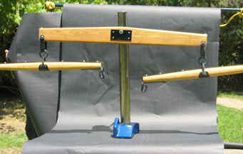
When the whiffletree is used in modern applications of precision engineering, the connections and the pivot points of the Whiffletree are usually Kinematic couples. In lightly loaded situations, flexures may suffice. Where some lateral freedom can be tolerated, knife-edges, can be an effective approach, but for all other applications the Kinematic coupling approach is the one best answer. The power of a sphere coupled to the Kelvin trihedral clamp, with its three degrees of constraint, that are provided by the three inclined prismatic faces, is the first choice for the central pivot. The second choice is the somewhat less expensive conical cup with its surface divided into three pads. Another excellent approach, when the load is light, is the three ball kinematic couple or the Rosebud version of the three ball couple, (see our catalog).
In most precision engineering applications, the Whiffletree system is used in compression, although it will work equally well in tension or even in hybrid applications. One of the most powerful features of the Whiffletree in precision engineering is its ability to turn a highly unstable four points of contact system with its good resistance to upsetting forces into a very repeatable and stable Kinematically compatible three points of contact system. When does a rocking beam (balance beam) become a whiffletree? Without a lot of reference data to consult, I would say that a rocking beam is actually the simplest form of whiffletree. In 1964 we were building what may have been the earliest air bearing coordinate measuring machine. The customer mandated that the machine be supported on four feet with a diameter of four inches each. To achieve the required machine accuracy, we had to lap the fifty four inch by thirty inch (1.37m by .762m) ways flat and coplanar to ten millionths of an inch, (250 nanometers).
Every time that we relocated the machine base, the geometry of the ways would twist and bend, many times our tolerance. This was due mainly to the instability of the four points of contact. To normalize the stresses placed on the frame of the machine by its own mass, we built a special support table. Two of the feet sat directly on the flat table top. The other two feet were supported at the ends of a Rocking Beam. This Beam was connected to the frame of the table through its contact with a rugged knife edge. This knife edge was placed in the very center of the beam, between the other two feet. The frame of the table was adjusted to exactly level the top of the ways and we had no further trouble with movement in the geometry of the machine structure. At that time we thought that we had actually invented this Rocking Beam, when we later realized that it was just one branch of a whiffletree.
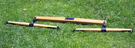
Wisdom is knowledge that we learn from others. If more of you would unselfishly publish your experiences, it would greatly reduce the reinvention of the wheel. There is a unique limitation to this simplest form of three contact, Whiffletree beam. When used in compression, all three Kinematic couples must have exactly the same centerline or the center sphere of the system must be above, but never below the centerline of the other two. Any deviation from this common centerline will lead to an unstable proclivity for off axis rotation. The simplest way to achieve this alignment is to place all three of the spherical elements on the beam. The whiffletree beam approach is very flexible, as the three spherical elements must simply have a common centerline, it does not require that they have common spherical diameters. The maximum number of contacts in a single Whiffletree branch is four and the minimum is three. Two or three contacts can be made with the driven element and one contact with the load element or visa versa. This small number of contacts is not a limitation as any number of Whiffletree branches may be coupled to a common load-carrying element.
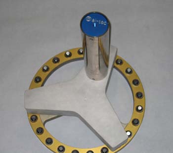
When large flimsy structures must be supported by a multiplicity of individual contacts, in order to maintain their form, a series of interconnected Whiffletrees can be the simple solution. When equalizing the support on a large mechanism the ideal design will consist of a Trivet or a series of interconnected Trivets with Kinematic couples on the top and bottom. An advantage of using the three legged trivet is that any off center tendency for rotation will be self correcting. A not so obvious option is that instead of two Trivets coupled to a Whiffletree beam, (Rocking beam) three Trivets may be coupled to another Trivet, thus multiplying the number of self adjusting, supporting contacts. The Whiffletree terminology doesn’t really coincide with the fundamental design of the trivet, so should we coin a new word, for this variation and call it a “trivetree” or is there already a name that we haven’t been exposed to, or is there already too much terminology?