Bal-tec™ Home All Probe Characterization Spheres
All Probe Characterization Spheres
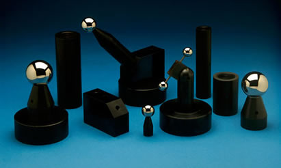
Probe Characterizing Spheres (aka probe calibration spheres, probe character sphere or datum spheres) are used to evaluate and determine compensation needed for errors in C.M.M. measuring probes. Most errors and problems on C.M.M.s are in the probe. This should be the first measuring device purchased to check the C.M.M.
How to Choose the Best Probe Calibration Sphere for Your Application
Sphere Diameter
The first consideration is to determine what diameter should the master calibration sphere be?
On most modern C.M.M.'s the probe fitting software will accept almost any diameter spherical master. The most common master spheres have been one inch, ( 1.00", 25.4 mm ), and three quarters of an inch, ( 3/4", 0.75", 19.05 mm ); but 28 mm (1.102 inches) and 30 mm (1.181 inches) diameter have become more popular as C.M.M. technology has taken on a more European focus.
The more popular sizes of master calibration spheres are less expensive. Changing the master calibration sphere diameter will not compromise the C.M.M.'s performance in any way. When using very small diameter spherical contacts on the measuring probe, choose much smaller diameter master calibration spheres to accurately characterize these small diameter contacts. The three most popular diameters for the master calibration spheres for smaller diameter probes are 4 mm ( 0.157 inch ), 6 mm (0.236 inch ) and 10 mm ( 0.3937 inch ). The smaller diameter master spheres are used to calibrate the smallest probe spheres and so on with the larger diameters. The problem of serious wear of the small diameter master spheres, due to the high contact force, makes it almost mandatory that these small diameter spheres be made of tungsten carbide. This is a necessary compromise because there will be some built in error due to the high stiffness of the T.C. material.
Sphere Material
The choice of material for the master calibration sphere can be of great importance, depending on the contact force of the measuring probe and its spherical diameter. The important factor in the choice of the material for the master calibration sphere is its stiffness. When the probe contacts the master calibration sphere, there is considerable Hertzian elastic deformation of both the master calibration sphere and the spherical contacts of the probe. The amount of these deformations depends mainly on the probe sphere diameter and the contact force of the measuring probe. The smaller the probe ball, and the higher the measuring force, the more elastic deformation will occur. If we use a very stiff material like ceramic or tungsten carbide for the master calibration sphere, and then measure ordinary materials such as aluminum or steel; we will loose appreciable accuracy. This built in error will be greater with the high measuring force typical of many of the modern scanning probes and will be higher for small diameter probe spheres than for the larger ones. The nearer the stiffness of the master calibration sphere matches the stiffness of the part being measured, the less error will result. For this reason, steel calibration spheres have been the order of the day until recently.
If the master calibration spheres are replaced in kind, all standard diameters of ceramic and tungsten carbide master calibration spheres are available.
Mounting the Ball
The next variable is choosing the design for the post used to hold the master calibration sphere. The one important word here is the rigidity of the post. What is needed, is a robust stiff structure that will still allow full access of the master calibration sphere by the measuring probe. When simple vertical or horizontal probes are being calibrated, the standard very rugged "PB" series calibration spheres on a very stiff post are the most accurate and the least expensive choice.
Slim Calibration Sphere
When calibrating more complex articulating probes and compound star probes, more complete access to the master probe calibration sphere is required. The first and least expensive of the complex probe calibration devices is the "Slim Probe" Calibration system. It consists of one or more master calibration spheres mounted on very slender, extremely high stiffness cermet rods. These one eighth of an inch 0.125" (3.2mm) diameter, extremely rigid cermets rods allow almost complete access to the periphery of the master calibration sphere or spheres. This more complex design and more expensive components cost about a 20% premium, over the standard PB series probe calibration spheres.
Star and Tree Probes
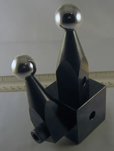
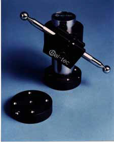
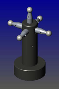
When the fastest most accurate calibration of complex star and tree probes is required, the device to specify is the "Star Probe Calibration Device". This arrangement uses five exactly matched master calibration spheres. One sphere is positioned vertically, and the other four are arranged horizontally at ninety-degree increments (see details of this device in the technical data sheet under C.M.M. products). The very rigid three quarter inch, 0.75" (19mm), mounting posts that hold the five master calibration spheres are securely fastened to a robust two inch, 2" (50.8 mm), diameter pole, that is in turn fastened to a four inch, 4" (101.6 mm), diameter ultra stable platform. The significance of this design is that the area of one master calibration sphere that is covered up by a support post is exactly opposite another matching calibration sphere, where that area is completely exposed. Subtract the fixed distance between the two spheres to get a 100% calibration of even the most complex probes.
Small Probe Calibration
Calibrating measuring probes with very small diameter contact tips requires small diameter master calibration spheres mounted on small diameter posts.
These parameters become even more critical when small diameter complex probes are used in the scanning mode. For these applications, a petite version of the star probe calibration device is available (see details under C.M.M. products).
Optical Probe Calibration
Optical probes form a very broad spectrum of devices, but they respond well to rather limited range of master calibration devices. The one "no no" for optical calibration devices is bright shiny artifacts. The least expensive calibration sphere is the satin finished stainless steel ball. Some optical probes respond very well to satin finished titanium, which has a very flat gray surface.
The most popular master calibration sphere for optical probes is satin finished aluminum oxide ceramic, which is very white but very dull. All of the metal balls suffer from the tendency to get burnished stripes on the surface that affect the calibration. This burnishing is caused by almost any physical contact with hard materials. This does not happen to the aluminum oxide ceramic. The very white surface of the ceramic ball gets dirty very quickly, but it can be easily cleaned with coarse hand soap. Very short Ball Bars (Dumbbells), with satin finished ceramic balls are a very popular calibration device. The post next to the balls is black oxide coated so they don't effect
To facilitate the holding of these very short Ball Bar (Dumbbell)s, we have developed the "Hammer." (See the technical data sheet under C.M.M. products). The Hammer has a right-angled post that is used to hold the Ball Bar (Dumbbell) in our standard clamping hardware. The characterization spheres are often ordered with and used with risers ( extensions ) and Dual Threaded Adaptor Screws.
Repair
We will remove a worn or damaged probe calibration ball and replace it with a brand new ball of the highest quality at a very reasonable price.
Custom
We will be pleased to quote you custom manufactured probe calibration spheres. These devices can be to your design, or we can replicate an existing product.
Calibration
We will inspect your probe calibration spheres for size and roundness. We will provide you with a long form inspection report that is traceable to N.I.S.T. for $65.00 each.
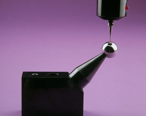
Using the Probe Characterizing or Calibration Sphere
This Probe Characterizing technique uses computer software and an extremely high quality spherical artifact of a well known diameter to calibrate the radius of the contact tip. It will characterize geometry errors of the measuring probe (probe lobbing), it will compensate for bending of the probe stem and a broad range of other elastic deflections or bending moments throughout the machine. The sphere is very rigidly fixed to the C.M.M. table for this test. In effect, the C.M.M.'s computer is told that it is measuring a perfect sphere of a specific diameter and that any departure from this ideal form should be corrected in all future measurements. Some C.M.M. software is written around a specific master sphere diameter while other software is open to selection by the user.
The most widely used sphere diameter is one inch (25.4mm) but 3/4 inch (19.05mm) is also widely used. In our experience down to about 10mm (.3937 inch) diameter, the smaller the master sphere used, the more accurately probe lobbing will be compensated for. This correction ends up being a simple adjustment in the apparent radius of the contact tip of the measuring probe.
Repeatability Test
This same spherical artifact makes an excellent Coordinate Measuring Machine repeatability test device. Its position on the table and its diameter are simply measured a considerable number of times (usually ten to twelve), and the results are compared. Each measurement consists of a small number of well distributed hits. Any variations in the measurements reflect a lack of machine repeatability. Valuable information about specific machine performance can be learned by looking at the end positions of individual axii. Note that this test must be performed as quickly as possible to avoid the influence of temperature drift.
The 2" By 2" Block
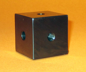
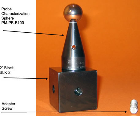
We offer the 2 inch by 2 inch universal mounting block, Part Number BLK-2, as an accessory for use with the probe calibration sphere hardware. The four threaded tie down holes are M10-1.5 thread. A through mounting hole with clearance for 10mm or 3/8 inch tie down bolt is provided. This approach to tie down allows the two inch square by two inch high block to be clamped down in any angular position.
The simplest application is to use it as a 2 inch riser to hold any of our probe calibration spheres. The 2" by 2" block can be used to mount any of our probe calibration spheres at right angles to the C.M.M. table. Mounting up to five of our standard probe calibration spheres creates an excellent star probe calibration device. Leaving it mounted on the CMM table with several of the calibration spheres attached provides a monument that will quickly provide proof of performance as an interim evaluation of your C.M.M.
Five sphere calibration spheres mounted on the 2" by 2" block, creates ten inter-sphere dimensions that are, in effect, ten unique length Ball Bars. The assembly of these 5 devices is a "pretzel" that exercises every function of your Coordinate Measuring Machine. Having the several extra probe calibration spheres available will provide you with the in house hardware to perform frequent temperature drift evaluations. Our entire family of probe calibration hardware is designed to be compatible with the 2" by 2" blocks.
Pricing
| Part # | Description | Price | Purchase |
|---|---|---|---|
| BLK-2 | 2 INCH BLOCK | $162.00 | |
45 Degree Angle Block Part Number: BLK-45
| Downloads | ||
|---|---|---|
| Solidworks | IGES | |
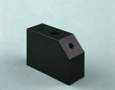
The 45 Degree Angle Block ( Part Number BLK-45 ) is used to hold Probe Characterizing Spheres inclined at 45 degrees, so they are more accessible for C.M.M. calibration. The block may be located in an out of the way place on the CMM table, while projecting the characterizing sphere out into the working zone of the machine.
This robust steel angle block is 3-1/2 inch ( 3.5", 88.9mm ) long by 1-1/2 inch (1.5", 63.5mm ) high and 1-1/2 inch ( 1.5", 38.1mm ) wide. Two tapped holes that are M10 inch diameter are provided to secure the characterizing sphere's 1-1/4 inch ( 1.25", 31.75mm ) diameter post. One tapped hole is provided in the center of the 1-1/2 inch ( 1.5", 38.1mm ) long 45 degree land, and one is provided in the top surface near the end opposite the 45 degree angle.
The base surface that locates this 45 degree block has areas of the surface relieved to leave three mounting pads. These pads are lapped flat and coplanar to form a stable clamping surface. A counterbored hole is provided through the height of the block. Using this counterbored hole, the 45 degree angle block is clamped solidly in position by 3/8 inch ( 0.375" ) or a 10 mm socket head cap screw. This 45 degree Block is designed to be used with the 4 inch ( 101.6 mm ) diameter steel platform, Part Number PLT4, see Technical Data Sheet The 45 degree Angle Block is supplied with an attractive black oxide finish which resists corrosion. The 45 degree Angle Block is generally purchased with dual threaded adaptor screws and a probe characterization sphere.
Pricing
| Part # | Description | Price | Purchase |
|---|---|---|---|
| BLK-45 | BLOCK, 45 DEGREE | $130.00 | |
The Abalone
The Abalone ( Part #10140 ) was originally developed as a clamping device for holding the Anchor and Ball Bar (Dumbbell) combinations on the tables of Coordinate Measuring Machines. Since then, it has found wide use for a variety of clamping and work holding tasks on C.M.M.s surface plates and machine tools. The Abalone is a powerful vacuum hold down device. When used with a good vacuum pump, the five inch diameter (127mm) base will provide over 290 pounds (131kg) of clamping force. The one and one quarter inch (31.75mm) thick aluminum device weighs only two pounds (.9 kilograms). It is hard coated and the base is precision lapped flat for good mechanical stability, long wear and to form a good vacuum seal that will assure the highest clamping force. A M10x1.5 threaded hole is provided in the top center of the Abalone to attach the Anchor. For added utility, there are four M10x1.5 drilled and threaded holes around the outer edge of the upper surface. These threaded holes facilitate the rigid mounting of other tooling.
Pricing
| Part # | Description | Price | Purchase |
|---|---|---|---|
| 10140 | ABALONE, 5" DIAMETER X 1.5" THICK | $165.00 | |
The Address Spheres
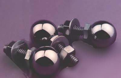
When three of these devices, also known as a tooling ball, (Part #A40320) are rigidly attached to diagonal corners of a Coordinate Measuring Machine pallet, it will exactly define the pallet's three dimensional address or position on the measuring machine table. The relative position of these threaded tooling balls defines the fixed location points that are used to exactly position the test part on the pallet system. This approach to locating these devices actually allow a pallet to be randomly positioned anywhere on the C.M.M. table, and yet the computer has a perfect knowledge of the test part's true three dimensional position. This location is retrieved from the data that was stored during the original measurement of the test part some time earlier.
The three exactly matched hardened stainless steel balls are three quarter inch ( 1.9 cm ) diameter. They are precision lapped spherical within less than five microinches and the surface is polished to a fraction of a microinch. The sphere is securely attached to the head of a short 1/4 inch (6.3 cm) diameter stainless steel bolt that has twenty threads per inch. To prevent a slight bump from separating the ball from the bolt, a 1/8 inch (3.2 mm) diameter pin extends well up into the ball and down into the bolt. A stainless steel washer and a jam nut are supplied with each threaded address sphere to rigidly fix their position on the pallet. In addition to their use for locating the position of a pallet on the C.M.M. table, these devices make an excellent measuring artifact and two or more of them left mounted on a pallet can form an interim checking device. A large array of these balls can be mounted on a simple piece of metal plate to construct a very high quality ball plate for Coordinate Measuring Machine Evaluation. When building a large artifact using many balls, the balls should be ordered as a single master set so that all spheres will be exactly the same diameter.
Address Sphere Pricing
| Part # | Description | Price | Purchase |
|---|---|---|---|
| A40320 | ADDRESS SPHERES, SET OF THREE | $151.00 | |
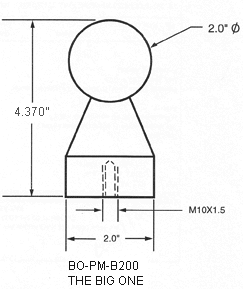
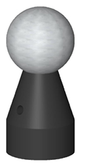
The Big One
Part Number BO-PM-B200
| Downloads | ||
|---|---|---|
| Solidworks | IGES | |
| N/A | ||
The "Big One" ( Part Number BO-PM-B200 ) is a giant 2.00 inch (50.8mm) diameter precision sphere mounted on a rugged 2.00 inch (50.8mm) diameter by 2-1/2 inch (63.5mm) high steel post. It was developed for the evaluation of Computer Numerically Controlled Machining Centers according to ANSI/ASME B 5.54.1992. It is also used as a probe characterizing sphere on some Coordinate Measuring Machines. The large target is particularly well-suited for use on big machines and on multi-spindle machines. Some of these tests include Machine Tool Repeatability, Temperature Variation Error, Hysteresis, Feature Accuracy, Pallet Change Repeatability, Tool Changer Repeatability, Drift, Vibration and Compliance.
The surface area of this 2.00 inch ( 50.8mm ) diameter sphere is 12.566 square inches ( 319.19 square mm ) which is four times the 3.1416 square inch (79.797 square mm) area of the standard 1.00 inch ( 25.4 mm ) diameter sphere commonly used. The 2.00 inch (50.8mm) diameter precision sphere is made of very fine grain high chrome, high carbon stainless steel that is hardened to 58 HRC for wear resistance and cold cycled for long-term dimensional stability. This large diameter component is lapped spherical within 5 millionths of an inch (127nm) and has a surface finish below 0.7 micro inches (17.78 nm) Ra. The exact diameter of the sphere can be certified to 10 millionths of an inch (254nm).
This design uses a unique high strength connection to join the precision sphere to the post. An Electrical Discharge Machine ( EDM ) is used to drill a concentric hole deep into the already finished sphere. This space age process uses millions of tiny bursts of electrical energy to erode a hole into the precision sphere without affecting the original quality. The end of the post has a corresponding hole drilled in it. As the high strength glue is applied to the assembly, a steel pin is inserted between these holes to form a very strong connection.
The flat base of the mounting post is recessed to leave an annular ring forming a stable connection for the sphere. The post of the "Big One" is provided with an attractive black oxide finish that resists corrosion. A 1/4 inch (6.35mm) diameter clearance hole is cross-drilled through the post and a high tensile stainless steel pin is provided to tighten and to remove the device from its mount. A M10 x 1.5 tapped hole is machined in the center of the flat base of the post to provide a strong means of attachment. This configuration is standard throughout the product line so that all components are interchangeable.
Pricing
| Part # | Description | Price | Purchase |
|---|---|---|---|
| BO-PM-B200 | BIG ONE, THE, 50.8 MM, 2 INCHES, 2.5 INCH POST | $431.00 | |
| BO-PM-SAT-B200 | BIG ONE, THE, SATIN FINISHED 50.8 MM, 2 INCHES, 2.5 INCH POST | $431.00 | |
| BO-EP-3 | BIG ONE, EXTENSION 3 INCHES, 2" DIAMETER | $37.40 | |
| BO-EP-6 | BIG ONE, EXTENSION 6 INCHES, 2" DIAMETER | $40.70 | |
CMM Probe Standard Extensions
Standard Extensions for Probe Characterizing, Part Numbers P-EP-2, P-EP-3, P-EP-6, BO-EP-3 & BO-EP-6, Extensions for CMM Probe Characterization Spheres
Standard Extensions ( risers ) raise and extend C. M. M. Probe Characterizing and C. N. C. Target Spheres. They are also used to securely couple measuring devices to the C. M. M. or C. N. C. table.
| Downloads | |||
|---|---|---|---|
| Part # | Solidworks | IGES | |
| BO-EP-3 | |||
| BO-EP-6 | |||
| P-EP-2 | N/A | N/A | N/A |
| P-EP-3 | |||
| P-EP-6 | |||
Three standard lengths of this version are available. The 2.00 inch (50,8mm) long version (Part Number P-EP-2), 3.00 inch (76.2mm) long version ( Part Number P-EP-3) and the 6 inch (152,4mm) (Part Number P-EP-6). The 1-1/4 inch ( 31.75 mm ) diameter extension posts have a 3/16 inch ( 4.76 mm ) clearance hole cross-drilled through the post diameter.
A high tensile stainless steel pin that passes through this hole is used to tighten and to remove the device from its mating part. Extensions for "The Big One"( Part Number BO-PM B200 ) are 2.00 inches ( 50.8 mm ) diameter to match its post. Two standard lengths of this version are available. The 3.00 inch ( 76.2 mm ) long version ( Part Number BO-EP-3 ) and the 6.00 inch (152.4 mm ) long version (Part Number BO-EP-6). The 2.00 inch ( 50.8 mm ) diameter extension posts have a 1/4 inch ( 6.3 mm ) diameter clearance hole cross-drilled through the diameter of the post. A high tensile stainless steel pin that passes through this hole is used to tighten and to remove the device from its mating part. Both ends of all extension posts are drilled and tapped M 10 x 1.5. This configuration is compatible with our full line of accessories. The center portions of both of the flat ends of all extension posts are recessed to leave annular ring. This flat ring forms a stable connection with the mating parts. All extensions are provided with an attractive black oxide finish which resists corrosion.
Pricing
| Part # | Description | Price | Purchase |
|---|---|---|---|
| BO-EP-3 | BIG ONE, EXTENSION 3 INCHES, 2" DIAMETER | $37.40 | |
| BO-EP-6 | BIG ONE, EXTENSION 6 INCHES, 2" DIAMETER | $40.70 | |
| P-EP-2 | EXTENSION, 2 INCHES, 1 1/4" DIAMETER | $38.15 | |
| P-EP-3 | EXTENSION, 3 INCHES, 1 1/4" DIAMETER | $38.15 | |
| P-EP-6 | EXTENSION, 6 INCHES, 1 1/4" DIAMETER | $39.44 | |
Dual Threaded Adaptor Screws
We carry a full line of Dual Threaded Adaptor Screws which have a different thread on each end. These threaded adaptors will match all of our Coordinate Measuring Machine evaluation and fixture building devices to the threads in the table of any C.M.M. or competitor's pallet system. The short version of these threaded adaptors (Table #1) have an overall length of 1.5 inches (38.1 mm) and each of the threads is 3/4 inch (19 mm) long, except the 1/4 inch-20 to M10 x 1.5, where the 1/4 inch diameter is only 1/2 inch (13 mm) long.
Pricing
| Standard Short-Threaded Adaptor: Table #1 | ||||
|---|---|---|---|---|
| Part # | Table Thread Size | Component Thread Size | Price | Purchase |
| S-8M-10M | M 8 x 1.25 x 3/4" ( 19 mm ) | M 10 x 1.5 x 3/4" ( 19 mm ) | $18.43 | |
| S-10M-10M | M 10 x 1.5 x 3/4" ( 19 mm ) | M 10 x 1.5 x 3/4" ( 19 mm ) | $18.43 | |
| S-12M-10M | M 12 x 1.75 x 3/4" ( 19 mm ) | M 10 x 1.5 x 3/4" ( 19 mm ) | $18.43 | |
| S-250-10M | 1/4" - 20 x 1/2" ( 13 mm ) | M 10 x 1.5 x 3/4" ( 19 mm ) | $18.43 | |
| S-312-10M | 5/16" - 18 x 3/4" ( 19 mm ) | M 10 x 1.5 x 3/4" ( 19 mm ) | $18.43 | |
| S-375-10M | 3/8" - 16 x 3/4 ( 19 mm ) | M 10 x 1.5 x 3/4" ( 19 mm ) | $18.43 | |
| S-500-10M | 1/2" - 13 x 3/4" ( 19 mm ) | M 10 x 1.5 x 3/4" ( 19 mm ) | $18.43 | |
Because these Dual Threaded Adaptor Screws get such heavy use, we machine a reduced-diameter on the very ends to avoid damaging the thread. The two threads have an undercut in the center to allow either of the threads to be tightened fully without any chance of binding. The Dual Threaded Adaptor Screws will not rust because they are manufactured from a very corrosive resistant type 18-8 Stainless Steel. The highest quality threads with increased tensile strength are produced by cold rolling the thread forms. There is a screwdriver slot provided at the end of each thread of the short version and in the long threaded end of the long version. With the aid of a coin or screwdriver, the Dual Threaded Adaptor Screw can be securely tightened into its mating part. The long version of these Dual Threaded Adaptor Screws have an overall length of 2.5 inches (76.2mm). The table, or short end thread, is 3/4 inch (1.9cm) long; and the M10x1.5 thread is 1.75 inches (44.5 mm) long, except the 1/4 inch-20 to M10x1.5, where the 1/4 inch diameter thread is only 1/2 inch (13mm) long.
If one of these fourteen combinations does not meet your requirements, we will be pleased to supply any other combination on special order.
| Standard Long-Threaded Adaptor: Table #2 | ||||
|---|---|---|---|---|
| Part # | Table Thread Size | Component Thread Size | Price | Purchase |
| L-8M-10M | M 8 x 1.25 x 3/4" ( 19 mm ) | M 10 X 1.5 X 1 3/4" ( 44.5 mm ) | $18.43 | |
| L-10M-10M | M 10 x 1.5 x 3/4" ( 19 mm ) | M 10 x 1.5 x 1 3/4" ( 44.5 mm ) | $18.43 | |
| L-12M-10M | M 12 x 1.75 x 3/4" ( 19 mm ) | M 10 x 1.5 x 1 3/4" ( 44.5 mm ) | $18.43 | |
| L-250-10M | 1/4" - 20 x 1/2" ( 13 mm ) | M 10 x 1.5" x 1 3/4" ( 44.5 mm ) | $18.43 | |
| L-312-10M | 5/16" - 18 x 3/4" ( 19 mm ) | M 10 x 1.5 x 1 3/4" ( 44.5 mm ) | $18.43 | |
| L-375-10M | 3/8" - 16 x 3/4" ( 13 mm ) | M 10 x 1.5 x 1 3/4" ( 44.5 mm ) | $18.43 | |
| L-500-10M | 1/2" - 13 x 3/4" ( 19 mm ) | M 10 x 1.5 x 1 3/4" ( 44.5 mm ) | $18.43 | |
The Large Magnetic Platform
Part Number: M-PLT4
Another popular target sphere that is compatible with this magnetic platform is the "Big One". It is particularly well-suited for the evaluation of large and multi-spindle machines. This device (Part Number PM-PB-B 200) incorporates a huge 2.00 inch (50.8 mm) diameter sphere mounted on a robust 2.00 inch (50.8 mm diameter by 2-1/2 inch (63.5 mm) high steel post. The surface area of this sphere is four times as great as the area of the standard 1.00 inch sphere. The surface area of a 1.00 inch (25.4 mm) sphere is 3.1416 square inches (79.797 square mm) and the surface area of the 2.00 inch (50.8 mm) diameter sphere is
The 4.00 inch (101.6 mm) diameter Magnetic Platform (Part Number M-PLT-4) is 1-1/2 inch (38.1 mm) thick and weighs over 5 lbs. (2.27 kg). A rare earth magnet provides a holding force of over 100 pounds (45.358 kg). Two pass-tipped jack screws are provided to assist in removing this powerful platform from the machine surface. As the jack screws are advanced, the soft pass tips press against the machine surface and smoothly raise the magnetic platform. It is provided with a M 10 by 1.5 threads per inch tapped hole in the center of the top surface and one near the outer edge. These threaded holes on the device are used to rigidly couple the various apparatus used with the platform. The top surface of the magnetic platform is machinable, so that additional threaded holes or other details can be added for specific applications. We will provide prompt delivery of special machined details to your specifications. The device is provided with an attractive black oxide finish that resists corrosion. The 45 degree angle block ( Part Number BLK-45, Technical Data Sheet CMM-11) and both the three inch ( 3.00", 76.2mm ) long ( part Number P-EP-3 ) and the six inch (6.00", 152.4 mm) long ( Part Number P-EP-6 ), 1-1/4 inch ( 1.25", 31.75 mm ) diameter extension posts are compatible with this platform. Both the 3.00 inch (76.2 mm) long (Part Number BO-EP-3), and the 6.00 inch (152.4 mm ) long ( Part Number BO-EP-3 )
| Part # | Description | Price | Purchase |
|---|---|---|---|
| M-PLT-4 | PLATFORM, MAGNETIC, 4" ( 101.6 MM ) DIAMETER, 1.5" ( 38.1 MM ) THICK | $326.00 | |
The Four Inch Universal Platform

| Downloads | ||
|---|---|---|
| Solidworks | IGES | |
The 4 inch platform ( part number PLT-4 ) is a universal mounting tool. It is used to securely couple a variety of measuring devices to the machine under test. Among these devices are all of the CMM probe characterizing spheres on a post including the Mini Ball Bar (Dumbbell). The 45 degree Angle block (Part Number BLK 45) is designed for use with the four inch ( 101.6 mm ) platform . For performance evaluation of Computer Numerically Controlled machining centers, it will hold the standard 1.00 inch ( 25.4 mm ), part number PM-UB-B100, diameter Ultra Precise Test Sphere on the 1-1/4 inch (31.75 mm ) diameter post. It will also hold "The Big One", a two inch ( 50.8 mm ) diameter Test Sphere mounted on a 2 inch (50.8 mm) diameter by 2-1/2 inch (63.5 mm ) high post.
All of these tools are coupled to the platform through a M10 x 1.5 diameter threaded stud. The platform has a tapped hole directly in the center and one near the outer edge of the top face. All of the accessories have corresponding tapped holes in them. In addition to the central counter bored hole, there are three 1/4 inch ( 6.35 mm ) diameter holes drilled through the platform and counterbored from the bottom. These three holes form the vertices of an equilateral triangle. They are used to mount three 3/4 inch ( 19.05 mm ) diameter truncated and tapped spheres to form the three Ball Kinematic Platform ( Part Number 3B-KM, Technical Data Sheet CMM-4) used in Ball Bar (Dumbbell) evaluation of Coordinate Measuring Machines.
This platform is manufactured from a free machining low alloy carbon steel. It may be easily modified to provide extra holes, threads, or other details. Prompt delivery of any modified configuration will be supplied at reasonable cost. This robust steel platform is four inches ( 101.6 mm ) diameter and 1-1/2 inch ( 38.1 mm ) thick. It weighs over five pounds ( 2.27 kg ). There is a recess machined in its base that leaves an annular ring around the edge. This ring is precision lapped flat to form an excellent coupling to a CMM or machine tool table.
There is a drilled and counterbored hole through the platform that will accept a 3/8 inch or a 10mm diameter socket head cap screw. This screw will securely clamp the platform to its mating surface. The 4" platform is supplied with an attractive black oxide finish which helps to retard corrosion. Other finishes are available on special order. The platform is often used with the Dual Threaded Adaptor Screws.
Pricing
| Part # | Description | Price | Purchase |
|---|---|---|---|
| PLT-4 | PLATFORM, 4 INCHES | $158.00 | |
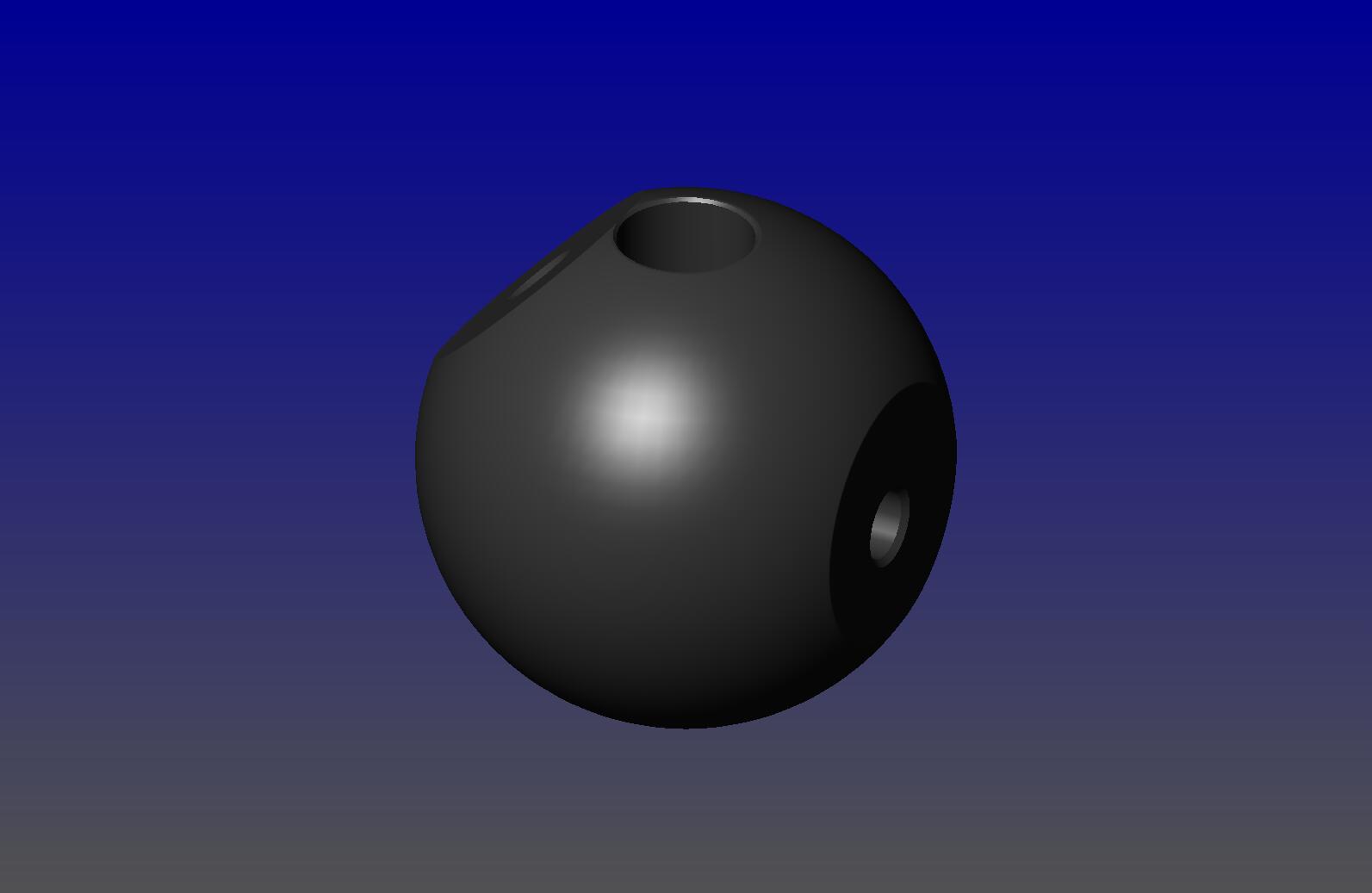
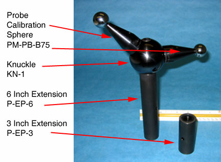
The Knuckle
| Downloads | |||
|---|---|---|---|
| Part # | Solidworks | IGES | |
| KN 1 | |||
| Extension | N/A | N/A | |
The Knuckle, our Part Number KN-1, provides a method for mounting the CMM calibration sphere. It is machined with a clearance hole for an M10 or 3/8" hex head cap screw. It is a made from a sphere with a flat at 90 degrees and a flat at 45 degrees. There is an M10 x 1.5 threaded hole in the center of each flat. It can be mounted directly on the CMM table, or it can be mounted on top of any length of our standard extension ( riser ) and dual threaded adaptor screws.
Pricing
| Part # | Description | Price | Purchase |
|---|---|---|---|
| KN-1 | KNUCKLE, THE | $74.80 | |
| P-EP-3 | EXTENSION, 3 INCHES, 1 1/4" DIAMETER | $38.15 | |
| P-EP-6 | EXTENSION, 6 INCHES, 1 1/4" DIAMETER | $39.44 | |
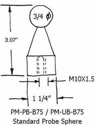
| PM-PB-B75 | PROBE CHARACTERIZATION SPHERE, STAINLESS STEEL, 19.05 MM, 0.75 INCHES | $253.00 | |
Mini Ball Bar Characterizes Complex CMM Probes
The contact probing system of a Coordinate Measuring Machine is characterized by evaluating a large number of measurements on the surface of a very precise sphere of known diameter. This precise sphere must be rigidly supported and held in a fixed position during the probe characterization process, otherwise misleading data will be collected.
This rigid support unavoidably covers up part of the spherical surface, which is therefore hidden from measurement by the contact probe. This hidden area is of no consequence when working with vertical probes, but it is of prime importance when the probe is inclined, horizontal or of compound, i.e. star design.
The simple solution to this problem is to use the Ball Bar (Dumbbell) concept as developed many years ago. This device uses two very precise spheres of exactly the same known diameter which are securely mounted on opposite ends of a rigid bar. This hidden area on the first sphere is exactly 180 degrees from the hidden area on the second, so 100% of the spherical surfaces are in effect available for probing.
The distance between the centers of the two spheres is absolutely constant. In effect, a measurement made on one sphere is exactly the same as a measurement made on the opposite sphere minus the fixed distance between the two centers. >The Mini Ball Bar (Dumbbell) is a versatile version of this device. It is offered in four standard spherical diameters - 1.00 inch ( 25.4 mm ) Part #MBB-100, .750 inch (19.05mm) MBB-75, 0.500 inch (12.7mm) MBB-50, and 10mm (0.3937 inch) MBB-39. Custom diameter spheres or combinations of two different spheres on the same Ball Bar (Dumbbell) will be quickly supplied at reasonable cost.
The Ultra-Precise Calibration spheres on the three larger diameter versions are produced from very fine-grained, high chrome, high carbon, stainless steel. They are hardened to 58 Rockwell C for wear resistance and ultra cold cycled for long term dimensional stability. The 10 mm (0.3937 inch) sphere is made from micro grain tungsten carbide. It is dimensionally stable, very corrosion resistant, and it is much more rigid and wear resistant than steel.
The 1/8 inch (0.125", 3.175mm) diameter shaft used to mount the two ultra-precise spheres is made of tungsten carbide. Because this very rigid material allows such a small diameter shaft to be employed, the maximum area of the spherical surface is exposed for measurement. It would require a steel shaft of .408 inch (10.36mm) diameter to match its rigidity.
The incline position of the Mini Ball Bar (Dumbbell) is adjustable through a broad angular range. In this way, the ideal position to match each probe configuration can be used. The bar can be quickly switched to the opposite side of the post so that compound, i.e. star probes can be accommodated without relocating the base. The 1-1/4 inch(1.25", 31.75mm) diameter by 4 inch (101.6mm) high rugged steel post has an M10 X 1.5 threaded hole in its base to fasten it to a mating surface.
A three inch (76.2mm) long by 1-1/4 inch (31.75mm) diameter extension post (Part# P-EP-3) and a 6" inch long extension post ( Part # P-EP-6) are available to raise the height of the Mini Ball Bar (Dumbbell) The rugged steel post that carries the Mini Ball Bar (Dumbbell) is coupled to the C.M.M. table through a robust steel platform ( Part # PLT-4 ) (see Technical Data Sheet CMM-6.A.). This platform is four inches (101.6 mm ) diameter by 1-1/2 inch ( 38.1 mm ) thick and weighs over five pounds ( 2.27 kg ). The bottom of this platform is machined to leave an annular ring around the outside. This ring is precision lapped flat to provide a very stable connection with the top of the C.M.M. table. An M10 x1.5 threaded hole through the center of the platform allows the post to be securely clamped to the
Another accessory available for use with the Mini Ball Bar (Dumbbell) is the 45 degree Angle Block ( Part# BLK-45 ) which is used to incline the sphere and In order to facilitate the connection and removal of the posts and extensions, a 3/16 inch (4.76mm) diameter clearance hole through the parts is provided. A removable steel pin made of high-tinsel stainless steel is supplied as a handle. An attractive black oxide finish is applied to the post and other accessories to help prevent corrosion.
Mini Ball Bar Pricing
| Part # | Description | Price | Purchase |
|---|---|---|---|
| MBB-39 | MINI BALL BAR, 10 MM, 0.3937 INCHES | $498.00 | |
| MBB-50 | MINI BALL BAR, 12.7 MM, 0.5 INCHES | $498.00 | |
| MBB-75 | MINI BALL BAR, 19.05 MM, 0.75 INCHES | $498.00 | |
| MBB-100 | MINI BALL BAR, 25.4 MM, 1 INCHES | $498.00 | |
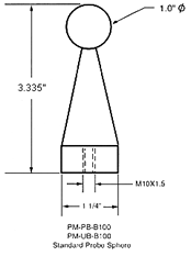
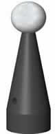
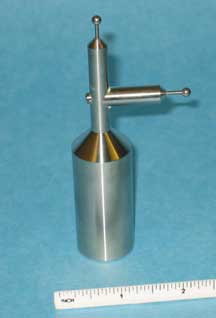
Probe Characterizing Spheres on a Post for Coordinate Measuring Machine
| Downloads | |||
|---|---|---|---|
| Part # | Solidworks | IGES | |
| PM-PB-B75 / PM-UB-B75 | |||
| PM-PB-B100 / PM-UB-B100 | |||
| PM-PB-B75R / PM-UB-B75R | |||
| PM-PB-B100R / PM-UB-B100R | |||
| BO-PM-B0-200 / PM-UB-B200 | |||
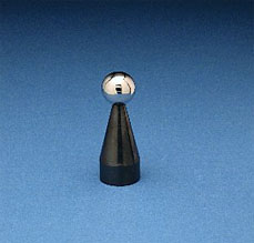
The PM series is the least expensive of the Coordinate Measuring Machine Probe Characterizing Fixtures. Despite its low price, this fixture is manufactured to the very highest quality standards.
The ultra precise datum spheres of either 1.00 inch ( 25.4 mm ) ( Part number PM-UB-B 100 ), or 0.750 inch ( 19.05 mm ) (PM-UB-B 75), or 0.500 inch ( 12.7 mm ) ( PM-UB-B 50 ) diameter use this common fixture. These spheres are made of very fine-grained, high carbon, high chromium stainless steel. It is through-hardened to 58 HRC for wear-resistance and ultra cold cycled for long-term dimensional stability.
The 10mm (0.3937") ( Part number PM-UB-B 39 ) sphere is made of micro-grained tungsten carbide and is mounted on a 0.125 inch (3.175mm) diameter tungsten carbide stem that is 0.850 inch This allows much greater measuring access to this smaller diameter sphere. The extremely high rigidity of tungsten carbide greatly reduces the elastic deformation of the smaller diameter sphere by the probe contact force, and yields a reduced bending moment of the support stem. Tungsten carbide is orders of magnitude more wear-resistant than hard steel. This material is very corrosion resistant, it will not rust.
The maximum departure from a perfect geometry on all of the Ultra Precise spheres is 2.5 micro inches (63.5 nm). This tolerance is considered to be the limit of commercial metrology. This is twice as accurate as the quality requirements for "Performance Evaluation of Coordinate Measuring Machines ANSI/ASME-B89.4.1-1997" and ten times as good as high quality bearing balls. The specific size of all of these balls is held to a tolerance of +0.000020" (508nm). The quality of the surface texture is maintained below 0.5 micro inches (12.7nm) Ra. Spheres of this quality are simply not available from any other commercial source.
In keeping with the very rugged design, the ball is not simply glued on top of the post, but is reinforced by a long metal pin that penetrates deep inside the ball and the post so that a minor tap will not send the ball rolling across the room. This hole is drilled in the ball using special computer-controlled Electrical Discharge Machining (EDM) techniques which do not disturb the original quality of the balls.
For maximum stability, the post of the probe characterizing sphere is supported by a robust steel platform. The post that supports the Ultra Precise Sphere and connects it to the platform is of rugged steel construction measuring 1-1/4 inch ( 1.25", 31.75 mm ) diameter at the base by 2-3/8 inch ( 2.375", 60.33 mm ) long. The extremely robust 4 inch ( 101.6mm ) diameter, 1-1/2 inch ( 1.5", 38.1 mm ) thick steel platform (Part Number PLT-4, ) is for a stable mount on the CMM table.
The central portion of the bottom of this platform is relieved to provide an annular ring of contact. The surface of this ring is precision lapped flat to provide the most stable location possible with the measuring machine table. This robust 5.2 pound ( 2.3 kg ) assembly has a counter-bored tie-down hole provided for either a 3/8 inch ( .375", 9.525 mm ) or a 10 mm diameter socket head cap screw.
In order to facilitate the connection and removal of the post, a 3/16 inch ( .1875", 4.76 mm) diameter clearance hole through the post is provided. A removable pin made of high tensile stainless steel is supplied as a handle.
Some accessories which are available for use with the probe characterizing spheres include a 45 Angle Block ( Part Number BLK-45 ) used to incline the sphere and post at an angle for easier access. A 1-1/4 inch ( 1.25", 31.77 mm ) diameter by 3 inch ( 76.2 mm ) long extension post ( Part Number P-EP3 ) and 6 inch ( 152.4 mm ) long extension post ( Part Number P-EP6 ) can be used to extend the height of the Probe
Probe Sphere Specifications
| Part # | Ball Diameter | Ball Material | |
|---|---|---|---|
| PM-PB-B75 | 19.0500 mm | 0.7500" | Hardened Stainless Steel |
| PM-PB-B100 | 25.4001 mm | 1.0000" | Hardened Stainless Steel |
| PM-UB-B39 | 10.0000 mm | 0.3937" | Tungsten Carbide |
| PM-UB-B50 | 12.7000 mm | 0.5000" | Hardened Stainless Steel |
| PM-UB-B75 | 19.0500 mm | 0.7500" | Hardened Stainless Steel |
| PM-UB-B100 | 25.4001 mm | 1.0000" | Hardened Stainless Steel |
| PM-UB-B100R | 25.4001 mm | 1.0000" | Hardened Stainless Steel, The Runt |
| PM-SAT-B50 | 12.7000 mm | 0.5000" | Hardened Stainless Steel |
| PM-SAT-B75 | 19.0500 mm | 0.7500" | Hardened Stainless Steel |
| PM-SAT-B100 | 25.4001 mm | 1.0000" | Hardened Stainless Steel |
| PM-SAT-B100-C | 25.4001 mm | 1.0000" | Ceramic |
| PM-SAT-B100-SN | 25.4001 mm | 1.0000" | Silicon Nitride |
| PM-SAT-B100-AO | 25.4001 mm | 1.0000" | Aluminum Oxide |
| PM-SAT-B100-ZO | 25.4001 mm | 1.0000" | Zirconium Oxide |
Probe Sphere Prices
| Part # | Description | Price | Purchase |
|---|---|---|---|
| PM-PB-B100 | PROBE CHARACTERIZATION SPHERE, STAINLESS STEEL, 25.4 MM, 1 INCHES | $253.00 | |
| PM-PB-B100-AO-R | PROBE CHARACTERIZATION SPHERE, RUNT, ALUMINUM OXIDE, 25.4 MM, 1.00 INCHES | $253.00 | |
| PM-PB-B100-C-R | PROBE CHARACTERIZATION SPHERE, RUNT, CERAMIC, 25.4 MM, 1 INCHES | $253.00 | |
| PM-PB-B100-R | PROBE CHARACTERIZATION SPHERE, RUNT, STAINLESS STEEL, 25.4 MM, 1 INCHES | $253.00 | |
| PM-PB-B75 | PROBE CHARACTERIZATION SPHERE, STAINLESS STEEL, 19.05 MM, 0.75 INCHES | $253.00 | |
| PM-PB-B75-C | PROBE CHARACTERIZATION SPHERE, CERAMIC, 19.05 MM, 0.75 INCHES | $253.00 | |
| PM-PB-B75-C-R | PROBE CHARACTERIZATION SPHERE, RUNT, CERAMIC, 19.05 MM, 0.75 INCHES | $253.00 | |
| PM-PB-B75-R | PROBE CHARACTERIZATION SPHERE, RUNT, STAINLESS STEEL, 19.05 MM, 0.75 INCHES | $253.00 | |
| PM-SAT-B100 | PROBE CHARACTERIZATION SPHERE, SATIN FINISH, 25.4 MM, 1 INCHES | $253.00 | |
| PM-SAT-B100-R | PROBE CHARACTERIZATION SPHERE, RUNT, SATIN FINISH, 25.4 MM, 1.0 INCHES | $253.00 | |
| PM-SAT-B50-R | PROBE CHARACTERIZATION SPHERE, RUNT, SATIN FINISH, 12.7 MM, 0.5 INCHES | $275.00 | |
| PM-SAT-B75 | PROBE CHARACTERIZATION SPHERE, SATIN FINISH, 19.05 MM, 0.75 INCHES | $253.00 | |
| PM-SAT-B75-R | PROBE CHARACTERIZATION SPHERE, RUNT, SATIN FINISH, 19.05 MM, 0.75 INCHES | $253.00 | |
| PM-SLM-UB-B100 | PROBE CALIBRATION SPHERE, SLIM, 25.4 MM, 1.00 INCHES | $201.00 | |
| PM-SLM-UB-B39 | PROBE CALIBRATION SPHERE, SLIM, 10 MM, 0.3937 INCHES | $219.00 | |
| PM-SLM-UB-B50 | PROBE CALIBRATION SPHERE, SLIM, 12.7 MM, 0.5 INCHES | $201.00 | |
| PM-SLM-UB-B75 | PROBE CALIBRATION SPHERE, SLIM, 19.05 MM, 0.75 INCHES | $201.00 | |
| PM-STAR-100 | STAR PROBE CALIBRATION ARTIFACT WITH 1.00" BALLS | $754.00 | |
| PM-STAR-75 | STAR PROBE CALIBRATION ARTIFACT WITH 0.75" BALLS | $644.00 | |
| PM-UB-B100 | PROBE CHARACTERIZATION SPHERE, ULTRA PRECISE, 25.4 MM, 1 INCHES | $275.00 | |
| PM-UB-B100R | PROBE CHARACTERIZATION SPHERE, RUNT, ULTRA PRECISE, 25.4 MM, 1.0 INCH | $275.00 | |
| PM-UB-B39-R | PROBE CHARACTERIZATION SPHERE, RUNT, ULTRA PRECISE, 10 MM, 0.393 INCHES | $253.00 | |
| PM-UB-B50 | PROBE CHARACTERIZATION SPHERE, RUNT, ULTRA PRECISE, 12.7 MM, 0.5 INCHES | $275.00 | |
| PM-UB-B50-R | PROBE CHARACTERIZATION SPHERE, RUNT, ULTRA PRECISE, 12.7 MM, 0.5 INCHES | $275.00 | |
| PM-UB-B75 | PROBE CHARACTERIZATION SPHERE, ULTRA PRECISE, 19.05 MM, 0.75 INCHES | $275.00 | |
| PM-UB-B75-R | PROBE CHARACTERIZATION SPHERE, RUNT, ULTRA PRECISE, 19.05 MM, 0.75 INCHES | $275.00 | |
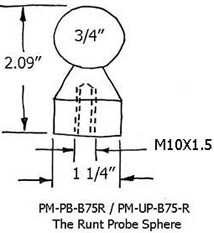
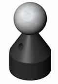
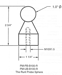
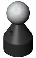
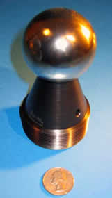
The Runt
The Runt™ fills the need for a shorter, more petite, probe characterization sphere for smaller Coordinate Measuring Machines ( CMM ) and for other special applications. The standard spherical diameter of the master ball is one inch (1.00", 25.4 mm ). The Runt™ is also available in a wide range of master ball diameters of both English and metric sizes to satisfy all requirements.
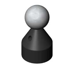
The overall height of the Runt™ equipped with a 1.00 inch ( 25.4 mm ) diameter sphere is only 2.35 inches ( 59.7 mm), which is a full inch shorter than the standard versions. Although it is manufactured to the highest quality standards, the Runt™ is sold for a very reasonable price. The quality of the sphere for the standard version of the Runt ( Part Number PM-PB-B100-R ) is held to a five microinch ( 127 mm ) sphericity which meets the quality requirements for the revised ANSI-B89.4.1- 1997 specification for the "Performance Evaluation of Coordinate Measuring Machines." The quality of the sphere for the Ultra Precision version of the Runt™ is two and one half microinch ( 63.5 nm ) sphericity which is state of the art for calibrating the test probes of the highest quality machines.
In keeping with the very rugged design, the ball is not simply glued on top of the post, but it is reinforced by a long metal pin that penetrates deep inside the ball and the post so that a minor tap will not send the ball rolling across the room. This hole is drilled in the ball by using the special computer controlled Electrical Discharge Machining (EDM) technique which does not disturb the original quality of the ball.
There is an MlOX1.5 threaded hole, in the base of the Runt™, which is used to rigidly fasten it to any mating surface. Through the use of our Dual Threaded Adaptor Screws, it can be adapted to the thread size of any C.M.M. table.
The Runt™ is compatible with the standard 1 1/4 inch ( 31.75 mm) diameter extensions of either the 3 inch (7.6 cm) long ( Part# P-EP-3 ) or the 6 inch (15.2cm) long ( Part# P-EP-6 ), the four inch diameter Platform, ( Part# PLT-4 ), the four inch diameter Magnetic Platform ( Part# M-PLT-4 ) or on the Abalone.
There is a 3/16 inch ( 0.1875", 4.8 mm ) diameter hole drilled at right angles through the post of the Runt™. A pin placed through this hole is used as a wrench to rotate the post to securely tighten or remove it. Except for the shorter overall length, this device has the same characteristics as the standard version of the post mounted calibration spheres.)
Probe Sphere Specifications
| Part # | Ball Diameter | Ball Material | |
|---|---|---|---|
| PM-UB-B100R | 25.4001 mm | 1.0000" | Hardened Stainless Steel |
| Downloads | ||
|---|---|---|
| Solidworks | IGES | |
| N/A | ||
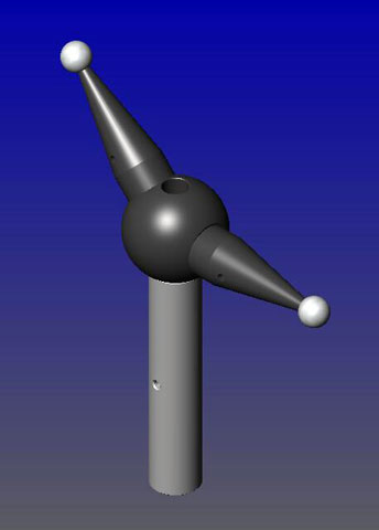
Star Probe CMM Calibration Artifact — Also Known as a Tree Probe
| Downloads | ||
|---|---|---|
| Solidworks | IGES | |
| N/A | ||
As the C.M.M. probes get more and more complex, the difficulty and complexity of calibrating them becomes more acute. A typical star probe has five probe spheres that must all be characterized in order to fully utilize the probe. In order to reach around, over and under all of these spherical contacts without moving the calibration sphere all over the place; a multi-sphere artifact must be used.
*Note that the platform shown, PLT-4, is included.By utilizing a set of five exactly matched calibration spheres that are arranged on orthogonal planes, this job can be done with relative ease. By building one ultra precise, ultra rigid universal artifact that can be used for calibrating even the most complex star probes; we have arrived at an economical approach to this dilemma. Many different diameter spherical artifacts can be used; but the most popular are three quarters of an inch 0.750 ( 19.05mm ) and one inch 1.00 ( 25.4mm ).
The spheres are normally produced from a very high chrome, high carbon Martensitic stainless steel. This ultra fine-grained material is through hardened to 58 HRC (Hardness on the Rockwell "C" scale) minimum. The material is subjected to a three cycle thermal stabilizing process to assure long-term dimensional stability. The sphericity and common size of the balls used on this artifact are held with five microinches (127 nanometers) with a 0.40 microinch (10 nanometers) Ra surface finish. The Young's Modulus of elasticity, or stiffness of these spheres is the same as that of steel parts, so that the highest level of measuring accuracy can be achieved.
This device is also available with ultra precise ceramic balls instead of steel. For calibrating various optical probes it is also available with satin finished steel, titanium, or ceramic balls. These optical target balls form a 3D artifact that is effective in evaluating the performance of the optical probe.
Pricing
| Part # | Description | Price | Purchase |
|---|---|---|---|
| PM-STAR-75 | STAR PROBE CALIBRATION ARTIFACT WITH 0.75" BALLS | $644.00 | |
| PM-STAR-100 | STAR PROBE CALIBRATION ARTIFACT WITH 1.00" BALLS | $754.00 | |
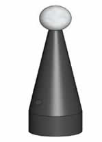
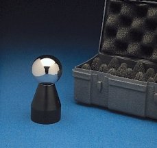
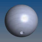
The Shielded Calibration Spheres — The Shielded Probe Spheres — The Guarded Calibration Ball — Master Ball with a Shield
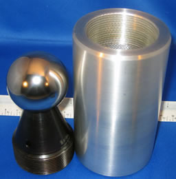
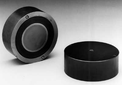
The shield on these probe spheres is provided to protect the Master Sphere from mechanical abuse and to keep coolant from degrading the strength of the adhesive holding the ball on the base. The shielded calibration spheres are designed for use in applications where the spheres are more or less permanently attached to the machine. The shielded calibration spheres are used as monuments that define exact positions of all three axii in the X, the Y and the Z. They find application for use with robots on the tables of machine tools and on Coordinate Measuring Machines ( CMM ).
One or more of these shielded master balls are mounted on the machine and periodically probed to validate the ball’s true position and the machine’s ability to measure the true diameter and position of the ball or balls.
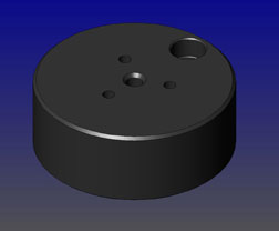
We offer two standard off the shelf versions of the Shielded Calibration Spheres. The smaller diameter version of the Shielded Calibration Sphere is our Part number SHD-PM-PB-100 which has a one inch (1.00”) [25.4mm] diameter master, Grade 5 sphere. The grade 5 designation means that the sphere is perfectly round within less than 5 millionths of an inch (0.0000127mm) and has a surface texture of less than 0.7 microinches Ra. The diameter of the base of this part is one and one quarter inch ( 1 1/4”, 1.250”) [31.75mm]. The annular ring that forms the bottom of this part is flat lapped within micro inches to provide the most stable design possible. The distance from the bottom of the base to the top of the ball is xxxx inch (xxxx mm).
There is a five sixteenths of an inch ( 5/16”, 0.3125”) [7.94mm] hole drilled at right angles through the body of the base. A cylindrical pin or the shank of an allen wrench can be used to rigidly attach these artifacts to the machine, or to remove the calibration sphere from the machine The shield is a two inch (2.00”) [50.8mm] diameter, screw on cap. It is made of Aluminum with an attractive anodized finish. This xxx inch (xxx mm) tall cap has a coarse knurled ring around the top to facilitate instillation and removal. In order to extend the elevation of the shielded Probe Sphere, we have available one and one quarter inch ( 1 1/4” 1.250”) [31.75mm] diameter.
- Our three inch [3.00”] (76.2mm) tall extension is part number P-EP-3.
- Our six inch (6.00”) [152.4mm] tall extension is part number P-EP-6.
The bottom of both of these extensions are threaded for an M10x1.5 hold down screw. The Big One version of the shielded calibration sphere is Part number SHD-PO-PM-B200. It has a two inch (2.00”) [76.2mm] diameter master sphere that is grade 5 quality. The grade 5 designation means that the sphere is perfectly round within 5 millionths of an inch (0.0000127mm) and has a surface texture of less than 0.7 microinches Ra. The base diameter of this part is two and one quarter of an inch (2.250”) [57.15MM]. The shield is a three inch (3.00”) [76.2mm] diameter screw on cap. This cap is made of aluminum with an attractive anodized finish. This xx inch (xxx mm) tall cap has a coarse knurled ring around the top to facilitate installation and removal. The annular ring that forms the base, is lapped flat within microinches, to provide the most stable possible connection to the machine. The standard probe sphere sizes can be altered to fit special customer needs. Satin finished balls can be supplied for compatibility with optical probes. More exacting quality spheres can be supplied for ultra precise applications.
Several types of ceramic master spheres as well as tungsten carbide are also available. The base is made of tough mild steel that is black oxided to reduce rust. The base is drilled and threaded for an M10-1.5 hold down screw. We manufacture a broad line of dual threaded adapter screws to facilitate the part's connection to almost any English ok metric thread. In order to extend the elevation of this 2 inch [50.4mm] diameter shielded Probe Sphere, we have available two inch (2”) [50.8mm] diameter extensions. Our three inch (3.00”) [76.2mm] high extension is part number P-EP-3.
Our six inch (6.0”) [154.4MM] high extension is Part number P-EP-6.
There is a five sixteenths of an inch (7.94 mm) hole drilled at right angles through the body of the base. A cylindrical pin or the shank of an Allen wrench can be used to rigidly tighten these artifacts down on the machine or to remove the calibration sphere from the machine. The master spheres are manufactured from an ultra fine grained, Martinsetic stainless steel. This steel is hardened to 58HRC minimum and three cycle cold stabilized. This heat treat and cold stabilizing assures that the exact diameter of the sphere will be maintained indefinitely.
Shielded Probe Sphere Pricing
| Part # | Description | Price | Purchase |
|---|---|---|---|
| SH-PS | SHIELDED PROBE SPHERE | $292.00 | |
| SH-BO | SHIELDED PROBE SPHERE, BIG ONE | $534.00 | |
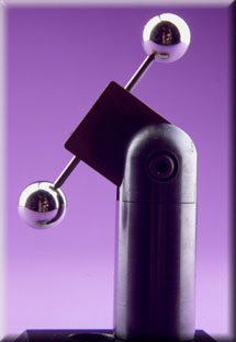
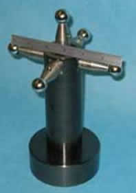
The Slim Calibration Sphere Tree Probe
For calibrating standard vertical or horizontal C.M.M. probes, our long time standard probe calibration sphere, part number PM-PB-B100 is the best inexpensive solution. When you must calibrate complex star probes or articulating probes, the long time standard probe calibration sphere comes up lacking; because the large rigid post we use covers up too much of the area of the probe calibration sphere. Most competitive companies have tried to solve this problem by using small diameter offset posts. This approach causes more problems than it solves. This is especially true when these posts are made of very low stiffness stainless steel. The bending of this spindly post by the probing force causes the sphere to measure much smaller than it really is. When the probe is compensated, using the true diameter of the calibration sphere, a substantial error is built into every future measurement.
The Slim Calibration Sphere solves these problems quite nicely. This is done by mounting the probe calibration sphere on a very small diameter rod of an extremely rigid material. By using this very simple fundamental of physics, we get excellent accessibility without the elastic deflection caused by the probing force. By building the support rod from a material that is almost four times as stiff as hardened steel, our one eighth of an inch diameter ( 3.175 mm ) support rod is equivalent to a .400-inch ( 10.16 mm) diameter steel post. The rugged one and one quarter inch (31.75 mm) diameter construction of the Slim Calibration Sphere base is compatible with all of our probe sphere hardware. This includes all extensions, bases and the 45-degree block. It is held in place by a large M10 X 1.5 (over 3/8 inch) socket head cap screw. This arrangement allows the sphere or spheres to be rotated into the ideal position for probing before locking the assembly down.
The simplest version of the Slim Calibration Sphere (our part number PM-SLM-) followed by the desired diameter of the calibration sphere required (1 inch, 20 mm, .5 inch, 10 mm etc.), cost of between $182.42 and $199.45 each. The simplest design has a single master sphere mounted at 45 degrees on a one-inch (25.4 mm) long, one eighth of an inch (1/8", 0.125", 3.175 mm) diameter extremely stiff rod. This device is also available with up to four calibration spheres mounted simultaneously. Simply specify the diameters of the desired spheres when ordering (each additional sphere costs $86.19 each). The calibration spheres can all be of the same diameter, or they can be of different diameters.
In very sophisticated C.M.M. Systems, two master spheres of exactly the same diameter, located 180 degrees apart, are used to calibrate the probe. The distance between the two spheres is fixed, so it can be subtracted when both spheres are probed. In this way the area where the post is located does not subtract anything from the characterization of the probe.
When calibrating really small diameter probing tips, there is a distinct advantage in using a much smaller diameter probe calibration sphere. For these applications a 10 mm (.3937 inches) or three eighths of an inch (9.53 mm) sphere is the usual choice. Because these small diameter spheres are so easily damaged, they are normally constructed of cemented tungsten carbide.
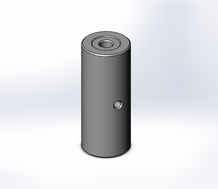
Precise and Ultra-Precise Calibration Spheres for Coordinate Measuring Machines and Master Balls — Spheres With Blind Holes
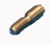
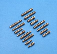
The proper Steel pin, ( 0.125", 3.18 mm diameter ) is supplied with each of the UB* and PB* series spheres. For the UB-B39, a 0.125 inch (31.75 mm) diameter by 0.850 inch (21.59 mm ) long tungsten carbide pin is supplied.
| Part #* | A - Dimension Ball Diameter + 0.000020" (+500NM) |
B - Dimension + 0.010" -.000" (+0.127 mm) (-0.000 mm) |
C - Depth + 0.010" (+0.254 mm) |
Ball Sphericity |
Ball Surface Quality |
Ball Material |
Price | Purchase |
|---|---|---|---|---|---|---|---|---|
| UB-B39 | 0.3937" 10 mm |
0.130" (3.302 mm) |
0.150" (3.810 mm) |
0.0000025" (63.5 NM) |
0.0000005" Ra. (12.5 NM) |
Tungsten Carbide |
$108.00 | |
| UB-B50 | 0.500" 12.7 mm |
0.130" (3.302 mm |
0.150" (3.810 mm) |
0.0000025" (63.5 NM) |
0.0000005" Ra. (12.5 NM) |
Hardened Stainless Steel |
$105.00 | |
| PB-B50 SAT-B50 |
0.500" 12.7 mm |
0.130" (3.302 mm) |
0.150" (3.810 mm) |
0.0000025" (63.5 NM) |
0.0000005" Ra. (12.5 NM) |
Hardened Stainless Steel |
$90.20 | |
| $90.20 | |
|||||||
| UB-B75 | 0.750" 19.05 mm |
0.130" (3.302 mm) |
0.250" (6.35 mm) |
0.0000025" (63.5 NM) |
0.0000005" Ra. (12.5 NM) |
Hardened Stainless Steel |
$105.00 | |
| PB-B75 SAT-B75 |
0.750" 19.05 mm |
0.130" (3.302 mm) |
0.250" (6.35 mm) |
0.000005" (125 NM) |
0.0000007" Ra. (17.5 NM) |
Hardened Stainless Steel |
$90.20 | |
| $90.20 | |
|||||||
| UB-B100 | 1.00" 25.4 mm |
0.130" (3.302 mm) |
0.250" (6.35 mm) |
0.0000025" (63.5 NM) |
0.0000005" Ra. (12.5 NM) |
Hardened Stainless Steel |
$105.00 | |
| PB-B100 SAT-B100 |
1.00" 25.4 mm |
0.130" (3.302 mm) |
0.250" (6.35 mm) |
0.000005" (125 NM) |
0.0000007" Ra. (17.5 NM) |
Hardened Stainless Steel |
$90.20 | |
| $90.20 | |
Replacement 45 ° Probe Calibration Sphere
This device is equal to or superior to any product on the market, but it is sold factory direct, for a fraction of competitive products. This xxx inch (xxx mm) tall, Probe Calibration artifact has the stem bent at a 45 degree angle to make the Master Sphere more accessible, for probing..
There are two off the shelf versions of this device. Part Number PM-PB-45-100 has 1.00 inch (25.4mm) diameter, very precise Grade 5 sphere. The Gr.5 sphere is absolutely round within five micro inches (0.000127mm), maximum and has a 0.7 micro inch (0.0000018mm) RA, maximum surface texture.
The ultra accurate 1.00 inch (25.4mm) diameter version of the 45 degree probe calibration sphere is our Part number PM-UB-45-100has a Grade 2.5 sphere. the grade 2.5 is spherical within 2.5 (two and one half) microinches [0.0000635mm], maximum and has a 0.5 micro inch (0.0000127mm) RA, maximum surface texture. This quality, is basically the most accurate sphericity that can be commercially measured.
The three quarter 0.750 inch (19.05mm) version of this device is Part number PM-PB-45-75. It uses a Grade 5 master sphere. It is absolutely round within 5 millionths of an inch (0.000127mm), maximum and has a 0.7 micro inch RA, maximum surface texture.
The ultra accurate three quarter inch diameter version of this part is Part Number PM-UB-45-75. It uses a grade 2.5 sphere. This sphere is absolutely round within two and one half millionths of an inch (0.0000635mm) maximum and has a maximum surface texture of 0.5 millionths of an inch (0.0000127MM) RA, maximum. The spheres for this artifact are produced from ultra fine grained martensetic stainless steel, that is hardened to 58 HRC minimum and three cycle cold stabilized for long term dimensional stability. This means that the diameter of these balls, will remain exactly the same size indefinitely.
This spherical artifact can be calibrated for size and roundness. This long form calibration can be certified with traceability to N.I.S.T. This part is a robust one, and one quarter inch (31.75mm) diameter (31.75mm) and is xxxx inches tall. The annular bottom surface, of this part is precision flat lapped within micro inches, to provide the most stable possible mounting. There is an M10-1.5 threaded hole, that is one half inch 1/2” (12.7mm) deep in the base, of this part, for mounting. This M10-1.5 thread can be matched with any other thread by using one of our dual threaded adapter screws. (See our web catalogue). The spheres are not just glued on the probe calibration post. The ball and the post are drilled with a one eight of an inch diameter hole, and the sphere is glued over this pin.
Replacement Probe Calibration Sphere
This device is equal or superior to any product on the market, but it is sold factory direct for a fraction of competitive products. These probe calibration spheres are a direct replacement for worn or damaged devices.
The one inch 1.00” (25.4 mm) spherical diameter version of the precision probe calibration sphere is our Part number PM-PB-LB100.
The three quarters of an inch ( ¾”, 0.750”, 19.06 mm ) diameter, version of the precision probe calibration sphere is our Part number PM-PB-LB75.
The 19 millimeter (0.74803 inch) spherical diameter, version of the precision probe calibration sphere, is our part number PM-PB-LB19M.
The 25 millimeter (0.98425 inch) spherical diameter, version of the precision probe calibration sphere, is our part number PM-PB-LB25M.
For calibrating normal commercial quality measuring machines, the very precise grade 5 spheres are used. These spheres are absolutely round within five millionths of an inch ( 0.000127 mm ) maximum. The surface texture on these spheres is less than 0.7 micro inches (0.0000177mm) RA maximum.
For calibrating the ultimate quality measuring machines, we offer our grade 2.5 spheres. These spheres are absolutely round within 2.5 millionths of an inch, (0.0000635mm), maximum. We consider this to be the highest quality roundness that can be measured commercially. The surface texture on these spheres is less than 0.5 micro inches (0.0000127mm) RA, maximum.
The ultra precise one inch 1.00” ( 25.4 mm ) spherical diameter version of the probe calibration sphere is our Part number PM-UB-LB-100.
The Ultra Precise three quarters of an inch ( 19.05 mm ) spherical diameter ultra precision version of the probe calibration sphere is our Part number PM-UB-LB-75.
The ultra precise 19mm (0.74803 inch) spherical diameter, version of the Probe Calibration sphere is our Part Number PM-UB-LB19M. the ultra precise 25 mm ( 0.98425 inch ) spherical diameter, version of the probe calibration sphere is our Part number PM-UB-LB-25M
The body of this device is made of alloy steel that is 30%, more rigid than the ordinary stainless steel versions sold by other companies. The body of this probe sphere is highly polished and then heavy nickel plating is applied, to eliminate any corrosion problems. The rugged body diameter of these devices is one and one quarter inch ( 1 ¼”, 1.25”, 31.75 mm). The base of these probe calibration spheres is precision flat lapped within micro inches to provide the ultimate locating surface.
One of the very important features of these devices is that the all of the precision stainless steel spheres used, match the exact stiffness of the steel and iron parts that you are measuring. This is unlike the common ceramic balls used on many of these devices. Ceramic balls are typically one third stiffer than iron or steel parts that you measure, so your machine will end up measuring the test parts slightly smaller than they actually are.
What this means is that the Hertzine elastic deformations of the master ceramic spheres that is caused by the contact force of the measuring probe will be far less than on the iron and steel parts being measured. The master sphere used on our probe calibration devices are constructed from micro grained Martinsetic stainless steel that is hardened to 58 HRC minimum and three cycle cold stabilized for long term dimensional stability. This means that the diameter of theses balls will remain exactly the same size, indefinitely.
The spheres are not just glued on top of the probe calibration post. The ball and the post are drilled with a one eights of an inch diameter hole ( 1/8”, 0.125”, 3.175 mm ) and the sphere is glued over this pin. We use a super strength, ceramic filled, epoxy glue, to fix the sphere rigidly to the base.